How does it work?
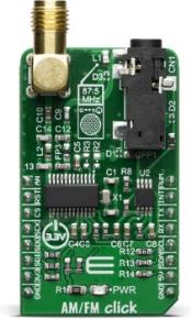
The AM/FM click is based on the Si4731 IC - digital CMOS AM/FM radio receiver IC integrates the complete broadcast tuner and receiver function from antenna input to digital audio output, from Silicon Labs. The audio signal from the output of the Si4731 is brought to a mini 3.5 female jack on board, over the LM4910 - an output oapacitor-less stereo 35mW headphone amplifier, from Texas Instruments. That way, it is ensured that user can plug in the headphones directly into the Click board™, without the need for any external amplifier.

The Si4731 IC The device leverages the Silicon Labs broadcast proven digital low-IF architecture, enabling a cost-effective, digital audio platform for consumer electronic applications with high TDMA noise immunity, superior radio performance, and high fidelity audio power amplification. Audio signal is processed to have the optimal dynamic qualities. The integrated DSP also takes care of the stereo MPX encoding and FM modulation of the signal. The low level digital intermediate frequency (IF) signal is then filtered out and sent to the outputs, that are is amplified, filtered, and digitized with high resolution analog-to-digital converters (ADCs). This advanced architecture allows the Si4731- to perform channel selection, FM demodulation, and stereo audio processing to achieve superior performance compared to traditional analog architectures.
The click is designed for communication over the I2C/2-wire control interface. When selecting 2-wire mode, SCLK pin should stay at a HIGH logic level during the rising edge on the RST pin, and stay HIGH until after the first start condition. Also, a start condition must not occur within 300nS before the rising edge on the RST pin. The 2-wire bus mode uses only the SCL and SDA pins for communication.
The Si4731 IC has the capability of the received signal measurement. The antenna which is used to broadcast the signal can also be used to accept the incoming signal, sent by the receiving device. Although it can be used both to receive and transmit signal, the antenna can't operate in both modes simultaneously. This feature can be useful when calibrating the transmission power of the click board.
This Click Board™ is designed to be operated only with 3.3V logic level. A proper logic voltage level conversion should be performed before the Click board™ is used with MCUs with logic levels of 5V.
Specifications
| Type |
FM |
| Applications |
Cellular phones, MP3 players, portable media players, wireless speakers, personal computers and any other applications, where audio broadcasting on the small distance is required. |
| On-board modules |
Si4731 IC - digital CMOS AM/FM radio receiver IC integrates the complete broadcast tuner and receiver function from antenna input to digital audio output, from Silicon Labs. |
| Key Features |
Easy to set, high quality integrated FM radio receiver. It uses advanced audio processing techniques to avoid over-modulation and to achieve perfect levels of audio signal. |
| Interface |
I2C,GPIO |
| Compatibility |
mikroBUS |
| Click board size |
M (42.9 x 25.4 mm) |
| Input Voltage |
3.3V,5V |
Pinout diagram
This table shows how the pinout on AM/FM click corresponds to the pinout on the mikroBUS™ socket (the latter shown in the two middle columns).
| Notes |
Pin |
 |
Pin |
Notes |
|---|
| General purpose Output 1 |
GP1 |
1 |
AN |
PWM |
16 |
NC |
|
| Device reset |
RST |
2 |
RST |
INT |
15 |
GP2 |
General purpose Output 2 Interrupt |
| I2C address selection |
SEN |
3 |
CS |
RX |
14 |
NC |
|
| |
NC |
4 |
SCK |
TX |
13 |
NC |
|
| |
NC |
5 |
MISO |
SCL |
12 |
SCL |
I2C Clock |
| |
NC |
6 |
MOSI |
SDA |
11 |
SDA |
I2C Data |
| Power Supply |
3.3V |
7 |
3.3V |
5V |
10 |
NC |
|
| Ground |
GND |
8 |
GND |
GND |
9 |
GND |
Ground |
Onboard settings and indicators
| Label |
Name |
Default |
Description |
|---|
| LD1 |
PWR |
- |
Power LED Indicator |
RS485 4 Click electrical specifications
| Description |
Min |
Typ |
Max |
Unit |
|---|
| Ambient temperature |
-20 |
|
85 |
°C |
| FM band support |
64 |
|
108 |
MHz |
| AM band support |
2.3 |
|
26.1 |
MHz |
| SNR |
53 |
58 |
|
dB |
| THD |
|
|
0.5 |
% |
Software Support
We provide a library for the AMFM Click on our LibStock page, as well as a demo application (example), developed using MikroElektronika compilers. The demo can run on all the main MikroElektronika development boards.
Library Description
Library contains function for sending commands and command arguments to device Library contains function for checking states of INT, AND, RST and CS pins Library contains function for receiving status byte of a device Library contains functions for checking states of specific interrupt bits in status byte Library contains function for receiving response bytes from a device Library contains function for device initialization Library contains function for seeking channels Library contains function for setting volume Library contains function for muting/unmuting device Library contains function for tuning frequency up/down Library contains function for getting current channel value Library contains constants for commands, arguments and properties.
Key functions:
uint8_t amfm_sendCommand( uint8_t * cmdAndArgsBuf_ ) - sends command and command arguments to deviceuint8_t amfm_getCts( void ) - checks CTS bit state and returns 0/1 if CTS bit did/did not go HIGH in less than 500 cyclesuint8_t amfm_getResponse( uint8_t * respBuf_, uint8_t nBytes_ ) - returns a device response into a respBuf_ after receiving CTS
Examples description
The application is composed of three sections :
- System Initialization - Initializes I2C, LOG, AN pin as INPUT, INT pin as INPUT, RST pin as OUTPUT, CS pin as OUTPUT
- Application Initialization - Initializes I2C driver and initializes the device
- Application Task - Executes aditional functions based on user input
void applicationTask( )
{
    dataReady = UART_Rdy_Ptr( );

if (dataReady != 0)
    {
        receivedData = UART_Rd_Ptr( );

    switch (receivedData)
        {
            case 's' :
            {
                amfm_caseSeek( );
                break;
            }
            case '+' :
            {
                amfm_casePlus( );
                break;
            }
            case '-' :
            {
                amfm_caseMinus( );
                break;
            }
            case 'm' :
            {
                amfm_caseMemorize( );
                break;
            }
            case 'i' :
            {
                amfm_caseMute( );
                break;
            }
            case 'u' :
            {
                amfm_caseTuneUp( );
                break;
            }
            case 'd' :
            {
                amfm_caseTuneDown( );
                break;
            }
            case '1' :
            {
                amfm_caseStation1( );
                break;
            }
            case '2' :
            {
                amfm_caseStation2( );
                break;
            }
            case '3' :
            {
                amfm_caseStation3( );
                break;
            }
            case '4' :
            {
                amfm_caseStation4( );
                break;
            }
            case '5' :
            {
                amfm_caseStation5( );
                break;
            }
            default :
            {
                mikrobus_logWrite( "> > > > > !!! WRONG COMMAND !!!  < < < < <", _LOG_LINE );
                break;
            }
        }
    }
}
Additional Functions :
- void amfm_caseMemorize( ) - memorizes up to 5 stations
- void amfm_caseStation1( ) - tunes station 1
- void amfm_caseStation2( ) - tunes station 2
- void amfm_caseStation3( ) - tunes station 3
- void amfm_caseStation4( ) - tunes station 4
- void amfm_caseStation5( ) - tunes station 5
- void amfm_caseSeek( ) - seeks next station
- void amfm_casePlus( ) - increases volume up to max value
- void amfm_caseMinus( - decreases volume down to min value
- void amfm_caseMute( ) - mutes the device
- void amfm_caseTuneUp( ) - increments station frequency for 10 KHz
- void amfm_caseTuneDown( ) - decrements station frequency for 10 KHz
The full application code, and ready to use projects can be found on our LibStock page.
Other mikroE Libraries used in the example:
Additional notes and informations
Depending on the development board you are using, you may need USB UART click, USB UART 2 click or RS232 click to connect to your PC, for development systems with no UART to USB interface available on the board. The terminal available in all MikroElektronika compilers, or any other terminal application of your choice, can be used to read the message.
mikroSDK
This Click board™ is supported with mikroSDK - MikroElektronika Software Development Kit. To ensure proper operation of mikroSDK compliant Click board™ demo applications, mikroSDK should be downloaded from the LibStock and installed for the compiler you are using.
For more information about mikroSDK, visit the official page.
Resources
Downloads