DIY SMD
Do-It-Yourself Surface-Mount-Device Assembly
 |
|
Please note that the advice in this article is followed at your own risk - the techniques described herein are, by their nature, not an exact science! With some care and common-sense however, great results can be achieved. |
The assembly of printed-circuit-boards (PCBs) involving surface-mount-devices (SMD) is normally performed by expensive and precise machinery.
Some companies have their own assembly facilities, and other companies (called "contract manufacturers") sell PCB assembly as a service.
For prototyping, or for the electronics enthusiast, both of these options may be impractically expensive. As well as being relatively expensive, the outsourcing of SMD assembly for small numbers of boards can result in long waiting periods before the assembled boards are returned.
It is not impossible however to perform surface-mount assembly using only
solder-paste and a
hot-plate.
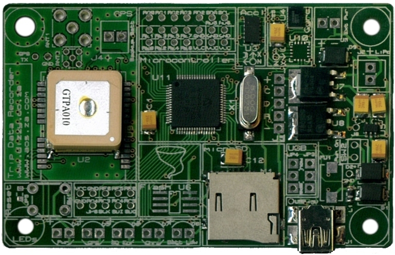
Above is a picture of a board assembled using
solder-paste, and a
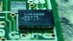
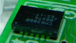
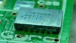
stove (some of the larger components were assembled manually using a soldering iron). Of special significance are the gyroscope and accelerometer at the top-right - these are impossible to mount using a soldering iron.
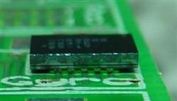
The tiny gyroscope (3 x 4mm, 10 pins, 0.5mm pitch) is shown in more detail below:
How It's Done
The technique is very simple, and essentially consists of applying some solder-paste, placing the components, and then heating the board up enough for the solder-paste to melt.
Solder-Paste Tips
If possible, try to get a solder-paste stencil for your board. This makes the correct application of solder-paste to the board much, much easier.
Beta-Layout provide free stencils with all boards which they make.
A solder-paste stencil jig can be made quite easily using a flat object (piece of wood / sheet-metal / etc) and two old PCBs. The PCBs are needed to get the right height spacing for the stencil, and should be placed at right-angles to each other. These should be mounted to your flat surface. The board to which you wish to apply solder-paste to is then pushed into the corner formed by the two PCBs, and the solder-paste stencil aligned correctly on top of it. A piece of sticky tape is then applied to the one edge of the stencil, in order to keep it in place and also act as a "hinge" so that the stencil can be easily lifted and boards moved into and out of
the jig.
The following tips apply especially if you do not have a solder-paste stencil available.
- It is important to try and get the quantity of solder-paste applied right. It is generally easier to resolder loose connections than it is to clean bridged connections, so the recommendation is to rather use too little than too much.
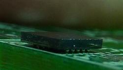
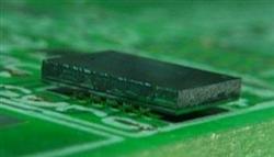
- It is sometimes easier to apply the solder paste to the component than it is to apply it to the PCB. This is illustrated in the following picture (accelerometer):
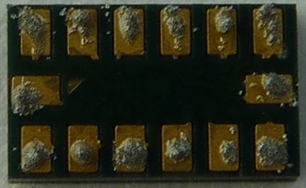
Some components (such as TQFPs) can have solder-paste applied to them by applying it across all the legs and then seperating it by running a pin between each of them (with the component held in the air).
Component Placement Tips
- It is generally ok to gently move the component around slightly once it has been placed in order to align it - the solder-paste should not be disturbed too much.
Heating Tips
- Try to place the board so that it is heated as evenly as possible.
- Apply maximum heat and watch the solder-paste. As soon as it has melted remove the board from the heat. When it is not possible to see the solder-paste (when it is under a component) then it can be helpful to place some as an indicator on an exposed part of the board nearby. Some areas will solder sooner than others, so try to make sure that the entire board has soldered before removing it from the heat. It may help to move the board around and/or turn down the heat once the first solder melts. Be careful not to leave the board on for too long, as the resin in the PCB could start to melt/burn and components could also possibly be damaged.
- As the solder-paste heats it may start to run and even bridge connections. These are normally resolved as the solder-paste melts and "pulls" towards the metal parts of the board/components. Similarly, components may be seen to "right" themselves. Some shorts can be easily resolved (whilst the solder is still molten) by running a pin between the legs where the short is occurring.
Post-Assembly Tips
- Be careful not to burn yourself by handling the board too quickly - leave it to cool down for a while.
- You may wish to check for short-circuits / loose connections with a multimeter. Loose connections can often be resolved by simply heating and depressing the component leg (if exposed) with a soldering iron. The board can also be re-heated, the component removed, and the assembly process retried.
 Further Information
The following points may also be of interest:
- Manual "pick-and-place" machines (far cheaper than automated ones), for relatively precise placement of components, are available.
- Small "reflow ovens", for more precise heating of the board, are available - Beta-Layout sell a "reflow kit".