The L20G20IS IC supports SPI interface which allows Gyro 4 click to be interfaced with a wide range of different MCUs. The IC interface is manufactured using a CMOS process that allows a high level of integration to design a dedicated circuit which is trimmed to better match the characteristics of the sensing element. It's perfect solution for optical image stabilization applications.
How does it work?
Gyro 4 click features L20G20IS two-axis MEMS gyroscope, from ST microelectronics. An angular rate gyroscope is a device that produces a positive-going digital output for counterclockwise rotation around the sensitive axis considered. Sensitivity describes the gain of the sensor and can be determined by applying a defined angular velocity to it. This value changes very little over temperature and time.
.jpg)
The zero-rate level describes the actual output signal if there is no angular rate present. The zero-rate level of highly accurate MEMS sensors is, to some extent, a result of stress to the sensor and therefore the zero-rate level can slightly change after mounting the sensor on a printed circuit board or after exposing it to extensive mechanical stress. This value changes very little over temperature and time. The L20G20IS includes temperature sensor and data can be retrieved from the registers, as two's complement data in 12-bit format left-justified. The output of the temperature sensor is 0 at 25 °C.
On the L20G20IS the angular rate data can be retrieved using a synchronous read. To perform a synchronous read, CTRL4_OIS (0Eh R/W) (DRDY_EN) has to be set to '1' in order to enable the data-ready interrupt on the INT pin. To properly perform a synchronous read, the angular rate data have to be read every time the DRDY pin goes high. The INT signal can be latched (default condition) or pulsed.
When a latched condition is selected, the interrupt goes low when the high part of one of the output channels is read and returns high when new data is generated. When a pulsed condition is selected, the interrupt behavior is independent from the read operations and remains high for 75 µs every time new data is generated. The INT pin is set by default as push-pull output, but it can be configured as open-drain output.
Specifications
| Type |
Motion |
| Applications |
It can be used to develop optical image stabilization or some similar applications. |
| On-board modules |
L20G20IS, is a two-axis MEMS gyroscope sensor IC, by STMicroelectronics |
| Key Features |
Integrated low-pass filters with user-selectable bandwidth, ±100 dps / ±200 dps full-scale range,embedded self-test… |
| Interface |
SPI |
| Click board size |
S (28.6 x 25.4 mm) |
| Input Voltage |
3.3V |
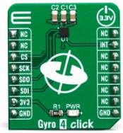
Pinout diagram
This table shows how the pinout on Gyro 4 click corresponds to the pinout on the mikroBUS™ socket (the latter shown in the two middle columns).
| Notes |
Pin |
 |
Pin |
Notes |
|---|
| |
NC |
1 |
AN |
PWM |
16 |
NC |
|
| |
NC |
2 |
RST |
INT |
15 |
INT |
INTERRUPT |
| SPI Chip Select |
CS |
3 |
CS |
RX |
14 |
NC |
|
| SPI Clock |
SCK |
4 |
SCK |
TX |
13 |
NC |
|
| SPI Data OUT |
SDO |
5 |
MISO |
SCL |
12 |
NC |
|
| SPI Data IN |
SDI |
6 |
MOSI |
SDA |
11 |
NC |
|
| Power Supply |
3.3V |
7 |
3.3V |
5V |
10 |
NC |
|
| Ground |
GND |
8 |
GND |
GND |
9 |
GND |
Ground |
Onboard settings and indicators
| Label |
Name |
Default |
Description |
|---|
| LD1 |
PWR |
- |
Power LED Indicator |
Software Support
We provide a library for the Gyro 4 click on our LibStock page, as well as a demo application (example), developed using MikroElektronika compilers. The demo can run on all the main MikroElektronika development boards.
Library Description
Library contains function for getting INT pin state Library contains function for setting CS pin state Library contains function for getting register values Library contains function for setting register values Library contains function for device initialization Library contains function for getting temperature value Library contains function for getting axes values Library contains function for software reset Library contains functions for setting power mode and full scale range
Key functions:
uint8_t gyro4_initialize( void ) - initializes the device.uint8_t gyro4_get_temperature( float * temperature ) - gets values of temperature registers and convets those values to [deg C].uint8_t gyro4_get_axes( float * x_axis, float * y_axis ) - gets values from axes registers and converts those values to [deg/s].
Examples description
The application is composed of three sections :
- System Initialization - Initalizes GPIO pins, SPI and LOG modules
- Application Initialization - Initializes SPI driver
- Application Task - Checks for data ready interrupt, gets axes and temperature data and logs those values
void applicationTask( )
{
    int_flag = gyro4_intGet( );
    while (int_flag == 1)
    {
        int_flag = gyro4_intGet( );
    }

    gyro4_get_temperature( &die_temperature );
    gyro4_get_axes( &x_axis, &y_axis );

    mikrobus_logWrite( " ", _LOG_LINE );

    FloatToStr( die_temperature, text );
    gyro4_floatCut( );
    mikrobus_logWrite( "> Die temperature : ", _LOG_TEXT );
    mikrobus_logWrite( text, _LOG_TEXT );
    mikrobus_logWrite( degrees_celsius, _LOG_LINE );

    FloatToStr( x_axis, text );
    gyro4_floatCut( );
    mikrobus_logWrite( "> X axis : ", _LOG_TEXT );
    mikrobus_logWrite( text, _LOG_TEXT );
    mikrobus_logWrite( degrees_per_second, _LOG_LINE );

    FloatToStr( y_axis, text );
    gyro4_floatCut( );
    mikrobus_logWrite( "> Y axis : ", _LOG_TEXT );
    mikrobus_logWrite( text, _LOG_TEXT );
    mikrobus_logWrite( degrees_per_second, _LOG_LINE );

    Delay_ms(500);
}
Additional Functions :
- gyro4_floatCut() - Rounds float number to two decimals
The full application code, and ready to use projects can be found on our LibStock page.
Other mikroE Libraries used in the example:
Additional notes and informations
Depending on the development board you are using, you may need USB UART click, USB UART 2 click or RS232 click to connect to your PC, for development systems with no UART to USB interface available on the board. The terminal available in all MikroElektronika compilers, or any other terminal application of your choice, can be used to read the message.
mikroSDK
This Click board™ is supported with mikroSDK - MikroElektronika Software Development Kit. To ensure proper operation of mikroSDK compliant Click board™ demo applications, mikroSDK should be downloaded from the LibStock and installed for the compiler you are using.
For more information about mikroSDK, visit the official page.
Resources
Downloads