Besides its protection features, MP9943 is also equipped with a soft-start function, and a sync option, making this Click board™ a very useful solution for the development of applications that require regulated 3.3V or 5V power supply. It can be used for a range of different applications: distributed power supply units (PSUs), wall transformer regulators, single board systems, general points of load, and similar applications that require regulated 3.3V or 5V power supply.
How does it work?
Buck 9 click is equipped with the MP9943, a synchronous step-down converter, from Monolithic Power Systems (MPS). This is an advanced integrated step-down converter, which requires a minimum number of external components, readily available on the market. It utilizes a peak-current-mode control architecture, which ensures an exceptional transient response and feedback loop stabilization. THE MP9943 buck converter features over-current, under-voltage, and thermal protection, making Buck 9 click a robust and reliable power supply solution.

The output voltage is determined by the feedback voltage on the FB pin. Buck 9 click is equipped with a voltage divider and an SMD jumper, labeled as VOUT. This jumper can be used to connect one of two available voltage divider resistors, allowing the output to be set to either 3.3V or 5V. These two voltages are the most commonly used in embedded development.
The over-current protection is based on cycle-by-cycle limiting of the inductor current. If the output voltage starts to drop during the current limiting interval, causing the FB voltage to drop under 84% of the internal reference, the device enters the hiccup mode, shutting down the output. After a fixed period, the device will try to re-enable the output. If the short-circuit condition still exists, it will shut down the output again, repeating the whole process, until the short-circuit condition disappears. The hiccup mode greatly reduces the short-circuit current, protecting the device when the output is shorted to ground.
Thanks to its ability to work with the high duty cycle of the internal switching PWM signal, the MP9943 requires the input voltage to be only about 0.7V above the output voltage, in order to maintain the regulation. However, if the input voltage drops under 3.3V, the device will not be able to operate properly. Therefore, the under-voltage protection shuts down the device, as a protection measure. The under-voltage protection is disabled once the input voltage exceeds 3.5V. This small hysteresis of 0.2V prevents erratic behavior in border-cases.
The MP9943 has some other advanced features, including synchronization with the external clock in the range from 200kHz up to 2.2MHz over the EN/SYNC pin. The same pin is also used as a Chip Enable for the device. The EN/SYNC pin is routed to the mikroBUS™ PWM pin, allowing to both synchronize and enable the MP9943 by the host MCU. The MP9943 operates at high (fixed) switching frequency of 410 kHz, which allows a good compromise between the efficiency and the size of the external components.
As mentioned before, the voltage of the power supply at the input terminal should stay within the range between 4V and 36V. However, if the output voltage is set to 5V, the voltage at the input should be approximately 5.7V to 6V at least, in order to provide a good regulation at the output.
Specifications
| Type |
Buck |
| Applications |
A very reliable regulated power supply for a range of different applications: distributed power supply units (PSUs), wall transformer regulators, single board systems, general points of load, and similar applications that require regulated 3.3V or 5V power supply. |
| On-board modules |
MP9943, a synchronous step-down converter, from Monolithic Power Systems (MPS) |
| Key Features |
Low power dissipation due to high efficiency, over-current, under-voltage, and thermal protection, selection between two most commonly used voltage values, etc. |
| Interface |
GPIO |
| Input Voltage |
3.3V |
| Click board size |
M (42.9 x 25.4 mm) |
Onboard settings and indicators
| Label |
Name |
Default |
Description |
|---|
| PWR |
PWR |
- |
Power LED indicator |
| VIN |
VIN |
- |
External PSU input connector |
| VOUT |
VOUT |
- |
Output connector |
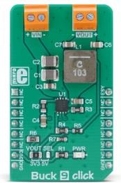
| JP1 |
VOUT SEL |
3.3V |
Output voltage selection: left position 3.3V, right position 5V |
Buck 9 Click electrical specifications
| Description |
Min |
Typ |
Max |
Unit |
|---|
| Input Voltage |
VOUT + 0.7 |
- |
36 |
V |
| Output voltage (VOUT) |
3.3 |
- |
3 |
V |
| Output current (continuous) |
0 |
- |
3 |
A |
Software support
We provide a library for the Buck 9 Click on our LibStock page, as well as a demo application (example), developed using MikroElektronika compilers. The demo can run on all the main MikroElektronika development boards.
Library Description
Library carries functions related to GPIO pins control of the Buck 9 click board. The library includes function for enable or disable device.
Key functions:
void buck9_deviceEnable(uint8_t state) - Function for enable or disable device.
Examples description
The application is composed of the three sections :
- System Initialization - Sets PWM pin as OUTPUT.
- Application Initialization - Initialization driver init and disable device.
- Application Task - (code snippet) - Enable and Disable device every 5000 ms.
Application Task - Predefined characters are inputed from the serial port. Depending on the character sent the signal frequency, waveform or amplitude will be changed.
void applicationTask()
{
     buck9_deviceEnable(_BUCK9_DEVICE_ENABLE);
     Delay_ms( 5000 );
     buck9_deviceEnable(_BUCK9_DEVICE_DISABLE);
     Delay_ms( 5000 );
}
The full application code, and ready to use projects can be found on our LibStock page.
Other mikroE Libraries used in the example:
Additional notes and informations
Depending on the development board you are using, you may need USB UART click, USB UART 2 click or RS232 click to connect to your PC, for development systems with no UART to USB interface available on the board. The terminal available in all MikroElektronika compilers, or any other terminal application of your choice, can be used to read the message.
mikroSDK
This click board is supported with mikroSDK - MikroElektronika Software Development Kit. To ensure proper operation of mikroSDK compliant click board demo applications, mikroSDK should be downloaded from the LibStock and installed for the compiler you are using.
For more information about mikroSDK, visit the official page.