The LARA-R202 module is fully qualified and certified solution which simplifies the design and cuts time to market. It is perfectly suited for a wide range of medium to high-speed M2M applications, such as the smart energy gateways, remote access video cameras, digital signage, telehealth, telematics, and similar applications which rely on a cellular network connection.
Note: The 4G LTE click versions for other regions and operators are also available.
How does it work?
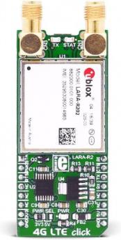
4G LTE click is equipped with the compact LARA-R2 series modem from u-blox. There are several click boards which covers different regions using different modules, as: North America - Verizon featuring LARA-R204, North America – AT&T featuring LARA-R202, Asia Pacific featuring LARA-R280, Europe featuring LARA-R211. The main difference between these modules are the supported frequency bands, compliant with the regulations for each region. A complete list of supported bands for each module, along with other relevant info about the module itself, can be found in the LARA-R2 series modem datasheet.
LARA-R2 series modem is the main component of the click board and it consists of a number of internal blocks or sections, such as antenna switching and signal conditioning section, RF transceiver section, memory, power management, and most importantly - the cellular baseband processor. This section contains the logic necessary for managing the other sections and provides the interface to the host MCU. This interface consists of several lines used to report the antenna status, sim card status, UART interface lines, reset line, USB interface lines... These lines are routed to the respective elements of the click board.
The LARA-R2 series module has to be powered with a clean and stable power supply. The voltage needed for the module to work properly is about 4V and it is derived from the 5V mikroBUSâ„¢ rail, through the MCP1826, a 1A low drop output (LDO) regulator from Microchip. Although the LARA-R2 series module is a low power device, the cellular network modules, in general, are notorious for their high power consumption, so the 1A LDO had to be used.
-click-inner-image.jpg)
Digital sections of the LARA-R2 series are internally supplied by 1.8V, so it is necessary to condition the communication bus lines which connect the host MCU with the module. For this reason, another small LDO is used, providing the needed reference voltage for one side of the TXB0106, a 6bit bidirectional level shifting and voltage translator with automatic direction sensing, from Texas Instruments. The reference voltage for the other side of the level shifter is taken from the onboard SMD jumper, labeled as PWR SEL. This jumper is used to select between 3.3V and 5V from the mikroBUSâ„¢, depending on the used MCU type and its logic voltage level requirements.
The UART bus of the LARA-R2 series module is connected to one side of the level shifter, while the other side (shifted) is connected to the respective mikroBUSâ„¢ UART pins. However, the LARA-R2 series module is designed as the traditional DCE device (Data Communication Equipment) offering the full UART pin count, including the hardware flow control pins (CTS, RTS). These pins are routed to the mikroBUSâ„¢ CS (RTS) and the INT pin (CTS) and can be used in the MCU software if the hardware flow control is needed. The RI pin is the ringing indicator, and it is routed to the mikroBUSâ„¢ PWM pin. Another set of modem control pins is routed to the mikroBUSâ„¢ pins, via the level shifter: RI is the ringing indicator pin, and it is routed to the mikroBUSâ„¢ PWM pin. This pin indicates the incoming call.
The STAT pin is used to signalize the network connection status. This pin is routed both to the mikroBUSâ„¢ AN pin through the level shifter, and the yellow LED used to visually indicate the status of the network connection. The transmitting status is indicated by the red TX LED, next to the STAT LED.
The PWRKEY pin is routed to the mikroBUSâ„¢ RST pin, and it is used during the power-up sequence. A low pulse on this pin will power up the device if the valid supply voltage is provided. To properly detach from the network and store the working parameters in its non-volatile memory, the module should be safely powered off by issuing the AT+CPWROFF command, before disconnecting the power source.
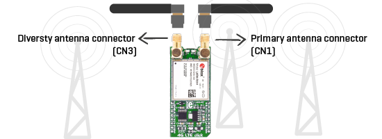
One distinctive feature of the E-UTRA physical radio layer used in LTE cellular networks is using the spatial multiplexing antenna technology which allows more than one antenna to be used for better reception of the specific frequency channel. Besides the primary TX/RX antenna, this click uses a secondary diversity RX antenna, which allows better signal reception.
4G LTE click is equipped with the micro USB connector. It allows the module to be powered and configured by a personal computer (PC). u-blox company offers a software suite that can be used to configure the LARA-R2 series module.
The Micro SIM card holder on the back of the click board™ is used to install a SIM card. This device can’t be used without the valid SIM card, which allows connection to the cellular network. Both 1.8V and 3V SIM card types are supported.
Free u-blox software
u-blox offers m-center, a free evaluation software for all their cellular modules. It has an easy-to-use graphical interface and can be used to configure the module and save changes to the EPROM. It is possible to view and edit SIM directory entries, send text messages, and communicate with the wireless module using AT commands.
4G LTE explained
Simply put, 4G is the fourth generation of the cellular network standard. It does not support traditional circuit-switched telephony service, it only supports the IP based communication, such as the IP telephony.
LTE (Long Term Evolution) technology, or 4G LTE as it is most commonly called, has been categorized as a 4G technology just recently. LTE has several different User Equipment (UE) categories defined. LARA-R modules are categorized as the LTE Cat 1 device.
If you are not familiar with cellular network standards and protocols and are not sure whether you need GSM or 3G or 4G, read our learn.mikroe.com article about 2G/3G/4G to get a better understanding.
Specifications
| Type |
GSM |
| Applications |
Medium to high speed M2M applications, such as smart energy gateways, remote access video cameras, digital signage, telehealth, telematics, and similar applications which can benefit from cellular network access |
| On-board modules |
LARA-R202 cellular module from u-blox |
| Key Features |
Data rates of up to 10.3 Mb/s for download and up to 5.2 Mb/s for upload, micro SIM card socket, dual SMA antenna connectors, micro USB connector, network detection, jamming detection, integrated data transfer protocols... |
| Interface |
USB,UART |
| Input Voltage |
3.3V,5V |
| Compatibility |
mikroBUS |
| Click board size |
L (57.15 x 25.4 mm) |
Pinout diagram
This table shows how the pinout on LTE-AT&T click corresponds to the pinout on the mikroBUSâ„¢ socket (the latter shown in the two middle columns).
| Notes |
Pin |
 |
Pin |
Notes |
|---|
| Module status |
STA |
1 |
AN |
PWM |
16 |
RI |
Ring indicator |
| Power up module |
PWK |
2 |
RST |
INT |
15 |
CTS |
UART Clear to send |
| UART Ready to send |
RTS |
3 |
CS |
RX |
14 |
TXD |
UART Transmit data |
| |
NC |
4 |
SCK |
TX |
13 |
RXD |
UART Receive data |
| |
NC |
5 |
MISO |
SCL |
12 |
NC |
|
| |
NC |
6 |
MOSI |
SDA |
11 |
NC |
|
| Power supply |
+3.3V |
7 |
3.3V |
5V |
10 |
+5V |
Power supply |
| Ground |
GND |
8 |
GND |
GND |
9 |
GND |
Ground |
Onboard settings and indicators
| Label |
Name |
Default |
Description |
|---|
| PWR |
PWR |
- |
Power LED indicator |
| TX |
TX |
- |
Transmit activity indicator |
| STAT |
STAT |
- |
Network status indicator |
| JP1 |
PWR SEL |
Left |
Logic voltage level selection: left position 3.3V, right position 5V |
Software support
We provide a library for 4G LTE-AT&T click on our Libstock page, as well as a demo application (example), developed using MikroElektronika compilers and mikroSDK. The provided click library is mikroSDK standard compliant. The demo application can run on all the main MikroElektronika development boards.
Library Description
The library carries generic command parser adopted for AT command based modules. Generic parser.
Key functions:
c4glte_cmdSingle - Sends the provided command to the module.c4glte_setHandler - Handler assignation to the provided command.c4glte_modulePower - Turns on the module.
Examples Description
Example demo application waits for the call. After the call is received the parser will get a hangup call.
This code snippet shows how generic parser should be properly initialized.
Before initialization, the module must be turned on and in addition to this, the hardware
flow control should also be turned on.
- The first command negotiates baud rate with the module.
- The second command turns echo off.
- The third command enables hardware flow control - necessary in case of UART polling.
- The fourth command sets up the default message format.
void applicationInit()
{
// MODULE POWER ON
 c4glte_hfcEnable( true );
 c4glte_modulePower( true );

// MODULE INIT
 c4glte_cmdSingle( "AT" );
 c4glte_cmdSingle( "ATE0" );
 c4glte_cmdSingle( "AT+IFC=2,2" );
 c4glte_cmdSingle( "AT+CMGF=1" );
}
Along with the demo application, timer initialization functions are provided. Note that timer is configured according to the default development system and MCUs, changing the system or MCU may require an update of timer init and timer ISR functions.
The full application code, and ready to use projects can be found on our Libstock page.
Other mikroE Libraries used in the example:
Additional notes and information
Depending on the development board you are using, you may need USB UART click, USB UART 2 click or RS232 click to connect to your PC, for development systems with no UART to USB interface available on the board. The terminal available in all MikroElektronika compilers, or any other terminal application of your choice, can be used to read the message.
mikroSDK
This click board is supported with mikroSDK - MikroElektronika Software Development Kit. To ensure proper operation of mikroSDK compliant click board demo applications, mikroSDK should be downloaded from the LibStock and installed for the compiler you are using.
For more information about mikroSDK, visit the official page.