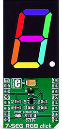
7-SEG RGB click carries a full-color single 7 segment digit display. The click is designed to run on either 3.3V or 5V power supply. It communicates with the target microcontroller over the CS, and PWM pin on the mikroBUS??? line.
The click can be connected in a chain, in order to display a larger number of characters. Unlike with conventional 7 segment displays, you will be able to use multiple colors on the display.
Display features
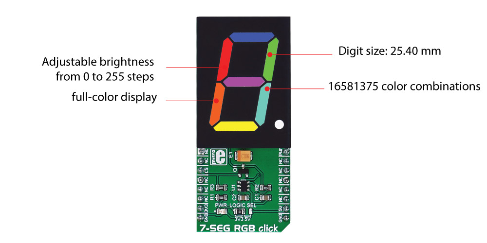
Each segment has R, G, B LEDs that can be adjusted in 255 steps and therefore 16,581,375 color combinations are available for each segment of the digit on the display.
Also, the ability to control the brightness of all the LED's is driven at 255 steps. It should be noted that the brightness values above 80 should rarely be used.
Specifications
| Type |
LED Segment |
| Applications |
Displaying digits and letters on a seven segment in full color |
| Brightness |
Adjustable from 0 to 255 steps |
| On-board modules |
RGBdigit full color single 7 Segment digit display |
| Key Features |
Multi-colored display |
| Interface |
PWM |
| Input Voltage |
3.3V or 5V |
| Click board size |
L (57.15 x 25.4 mm) |
Pinout diagram
This table shows how the pinout on 7-SEG RGB click corresponds to the pinout on the mikroBUS??? socket (the latter shown in the two middle columns).
| Notes | Pin |  | Pin | Notes |
|---|
|
NC |
1 |
AN |
PWM |
16 |
PWM |
Data input |
|
NC |
2 |
RST |
INT |
15 |
NC |
|
| Write enable (active low) |
CS |
3 |
CS |
TX |
14 |
NC |
|
|
NC |
4 |
SCK |
RX |
13 |
NC |
|
|
NC |
5 |
MISO |
SCL |
12 |
NC |
|
|
NC |
6 |
MOSI |
SDA |
11 |
NC |
|
| Power supply |
+3.3V |
7 |
3.3V |
5V |
10 |
+5V |
Power supply |
| Ground |
GND |
8 |
GND |
GND |
9 |
GND |
Ground |
Jumpers and settings
| Designator | Name | Default Position | Default Option | Description |
|---|
| JP1 |
Logic level |
Left |
3.3V |
Data in level Voltage Selection 3V3/5V, left position 3V3, right position 5V |
Programming
Code examples for 7-SEG RGB click, written for MikroElektronika hardware and compilers are available on Libstock.
Code snippet
The following code snippet writes the numbers 1, 2 and 3 in green, red and blue colors on 7-SEG RBG click.
01 #define ONE     0x06
02 #define TWO     0x5B
03 #define THREE   0x4F
04 sbit CS_BIT at GPIOD_ODR.B13;
05 sbit RGB_CONTROL_BIT at GPIOA_ODR.B0;
06 void systemInit()
07 {
08     GPIO_Digital_Output( &GPIOD_BASE, _GPIO_PINMASK_13 );
09     GPIO_Digital_Output( &GPIOA_BASE, _GPIO_PINMASK_0 );
10 }
11 void RGB_7_SEG_Init()
12 {
13     RGB_CONTROL_BIT = 0;
14     CS_BIT = 0;
15 }
16 void RGB_7_SEG_Task()
17 {
18     setSevenSegment(ONE,40,0,0);
19     Delay_ms(1000);
20     setSevenSegment(TWO,0,40,0);
21     Delay_ms(1000);
22     setSevenSegment(THREE,0,0,40);
23     Delay_ms(1000);
24 }
25 void main()
26 {
27     systemInit();
28     RGB_7_SEG_Init();
29     while( 1 )
30     {
31         RGB_7_SEG_Task();
32     }
33 }