This Click board™ is optimized for driving brushed DC motors. it integrates an efficient H-Bridge with very low ON resistance of approximately 500m? through each branch. An integrated sleep mode is activated when both logic inputs are at a LOW logic level for longer than 1ms, reducing the overall power consumption. A dedicated, high-precision current sensing amplifier IC is used to sense the current through motor coils, allowing the host MCU to perform current monitoring at all times. DC Motor 9 click is perfectly suited for rapid development of various DC motor driving applications, including home appliances, printers, industrial equipment, mechatronic applications, etc.
How does it work?
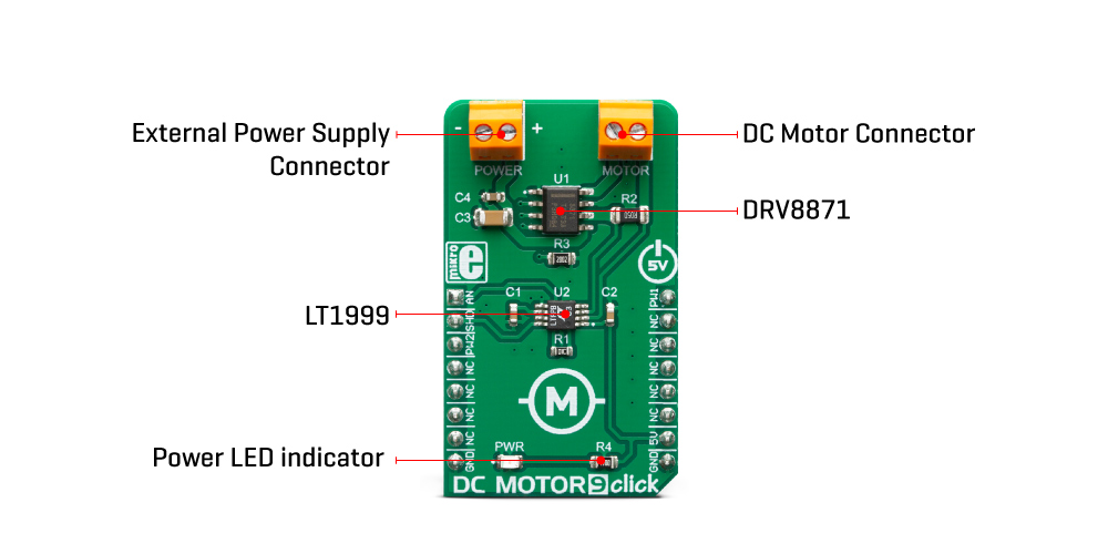
DC Motor 9 Click is designed around two different ICs: the first IC is the DR8871, a brushed DC motor driver, with internal current sensing, by Texas Instruments. This IC is actually an integrated H-Bridge driver with the current regulation circuit that allows limiting the current through the connected load, with just a single resistor. Unlike many other solutions, no external sensing resistors are required. A very low ON resistance through the H-Bridge reduces the overall power dissipation, while an advanced control circuit injects dead-time intervals, whenever the outputs change their state, preventing current shoot-throughs. The DRV8871 integrates a set of protection features, including undervoltage, overcurrent, and overtemperature protection. Each of these events will cause the H-Bridge MOSFETs to be disabled. After a fault condition has been removed, the device will continue its operation.
There are two methods that can be used to control the motor: the first method consists of applying a constant logic level to IN1 and IN2 inputs. While one of the inputs is held at a HIGH logic level, the other should be held at a LOW logic level. The direction of the motor rotation depends on which input is at the HIGH logic level. The second method consists of holding one pin to the LOW level while applying a PWM signal to the other. By changing the PWM frequency, it is possible to control the speed of the motor, while the direction of the motor rotation is determined by the pin the PWM signal is applied to.
Both pins to HIGH will set all the MOSFETs in HIGH-Z mode (coast) allowing the backEMF generated current to return to the source through the MOSFET body diodes. If both IN1 and IN2 pins are set to the LOW logic level, the connected motor is in a braking state. When the PWM signal is applied, the motor will be switched between the braking and rotating mode, causing it to slow down, depending on the pulse width of the applied PWM signal. The frequency of the PWM signal can range between 0 and 200 kHz, with the limitation that the PWM pulses must stay above 800ns for proper detection.
Current through the connected load is internally limited to maximum 3.6A. Higher current will cause the overcurrent protection to be activated. Peak current through the motor is limited to about 3.2A, ensuring reliable spin-up while preventing the overcurrent protection to be activated, even if a large load torque is applied. Although there is a very low resistance across the H-Bridge, the current should be monitored to prevent excessive heating in situations where the load is reasonably high.
Therefore, an additional IC is added, allowing the current to be monitored. The Click board™ uses the LT1999, a bidirectional current sense amplifier from Analog Devices (Linear Technology division). It is used to amplify voltage drop across the shunt resistor, so it can be accurately sampled. The output of the LT1999 IC is routed to the AN pin of the mikroBUS™, allowing the host MCU to sense the current by using its integrated ADC module.
Specifications
| Type |
DC |
| Applications |
DC Motor 9 click is perfectly suited for rapid development of various DC motor driving applications, including home appliances, printers, industrial equipment, mechatronic applications, etc. |
| On-board modules |
DR8871, a brushed DC motor driver, with internal current sensing, by Texas Instruments; LT1999, a bidirectional current sense amplifier from Analog Devices. |
| Key Features |
The main IC features a set of protection features, allowing for reliable performance. It allows the motor current to be monitored at all times. It also features high efficiency, it can be operated within a wide voltage range. |
| Interface |
Analog,GPIO |
| Input Voltage |
5V |
| Click board size |
M (42.9 x 25.4 mm) |
Pinout diagram
This table shows how the pinout on DC Motor 9 Click corresponds to the pinout on the mikroBUS™ socket (the latter shown in the two middle columns).
| Notes |
Pin |
 |
Pin |
Notes |
|---|
| Current sense |
AN |
1 |
AN |
PWM |
16 |
PW1 |
Control IN 1 |
| |
NC |
2 |
RST |
INT |
15 |
NC |
|
| Control IN 2 |
PW2 |
3 |
CS |
RX |
14 |
NC |
|
| |
NC |
4 |
SCK |
TX |
13 |
NC |
|
| |
NC |
5 |
MISO |
SCL |
12 |
NC |
|
| |
NC |
6 |
MOSI |
SDA |
11 |
NC |
|
| |
NC |
7 |
3.3V |
5V |
10 |
5V |
Power supply |
| Ground |
GND |
8 |
GND |
GND |
9 |
GND |
Ground |
DC Motor 9 Click electrical specifications
| Description |
Min |
Typ |
Max |
Unit |
|---|
| Input voltage |
6.5 |
|
45 |
V |
| Current through the load |
0 |
|
3.2* |
A |
Note: Large current through the connected load can result in significant power dissipation. Maximum current rating should be considered in respect with the power dissipation and heating.
Onboard settings and indicators
| Label |
Name |
Default |
Description |
|---|
| LD1 |
PWR |
- |
Power LED Indicator |
| TB1 |
POWER |
- |
External PSU connector |
| TB2 |
MOTOR |
- |
DC Motor connector |
Software support
We provide a library for the DC Motor 9 Click on our LibStock page, as well as a demo application (example), developed using MikroElektronika compilers. The demo can run on all the main MikroElektronika development boards.
Library Description
Library contains functions for setting CS and RST pins to HIGH or LOW level.
Key functions:
void dcmotor9_csSet( uint8_t pinState ) - Sets CS pin state to HIGH or LOW.void dcmotor9_rstSet( uint8_t pinState ) - Sets CS pin state to HIGH or LOW.
Examples description
The application is composed of the three sections :
- System Initialization - Initializes LOG, PWM pin as output, RST pin as input and CS pin as output.
- Application Initialization - Initializes GPIO driver and ADC and PWM functionalities.
- Application Task - Executes dcmotor9_getVoltAmperWatt( ) - function.
void applicationTask( )
{
    _adcValue = dcmotor9_adcRead( );
    WordToStr( _adcValue, text );
    mikrobus_logWrite( text, _LOG_TEXT );
    mikrobus_logWrite( " ", _LOG_LINE );
    Delay_ms(750);
}
Additional Functions :
dcmotor9_init( ) - Initializes PWM and ADC.dcmotor9_getVoltAmper( float adcRef ) - Performs ADC measurements and converts them to values of current and voltage.
Notes:
- Change pwm frequencty (uint16_t _frequency) from 0 to some value.
- Change pwm duty cycle (_dutyCycle = _maxDuty) from _maxDuty to value in range from 0 - _maxDuty.
- Optional : call - dcmotor9_getVoltAmper( adcRef ) - function to get value of voltage and current on shunt.
- float adcRef - is ADC value read from AN pin while no load is connected to device.
The full application code, and ready to use projects can be found on our LibStock page.
Other mikroE Libraries used in the example:
Additional notes and informations
Depending on the development board you are using, you may need USB UART click, USB UART 2 click or RS232 click to connect to your PC, for development systems with no UART to USB interface available on the board. The terminal available in all MikroElektronika compilers, or any other terminal application of your choice, can be used to read the message.
mikroSDK
This click board is supported with mikroSDK - MikroElektronika Software Development Kit. To ensure proper operation of mikroSDK compliant click board demo applications, mikroSDK should be downloaded from the LibStock and installed for the compiler you are using.
For more information about mikroSDK, visit the official page.