ADC 4 click is an advanced analog to digital multichannel converter, which can sample inputs from 16 single-ended channels or 8 differential input channel pairs. This device has a quite high sampling resolution of 24 bits and the output data rates can range from 5 SPS to 250 kSPS. Besides the internal 2.5V reference voltage source, ADC 4 click is also equipped with an external reference voltage circuit, which provides 4.096V. Finally, a custom reference voltage - up to 5V can be connected to the multiplexed inputs of the ADC converter. These options give a lot of flexibility in choosing the right reference voltage for any application.
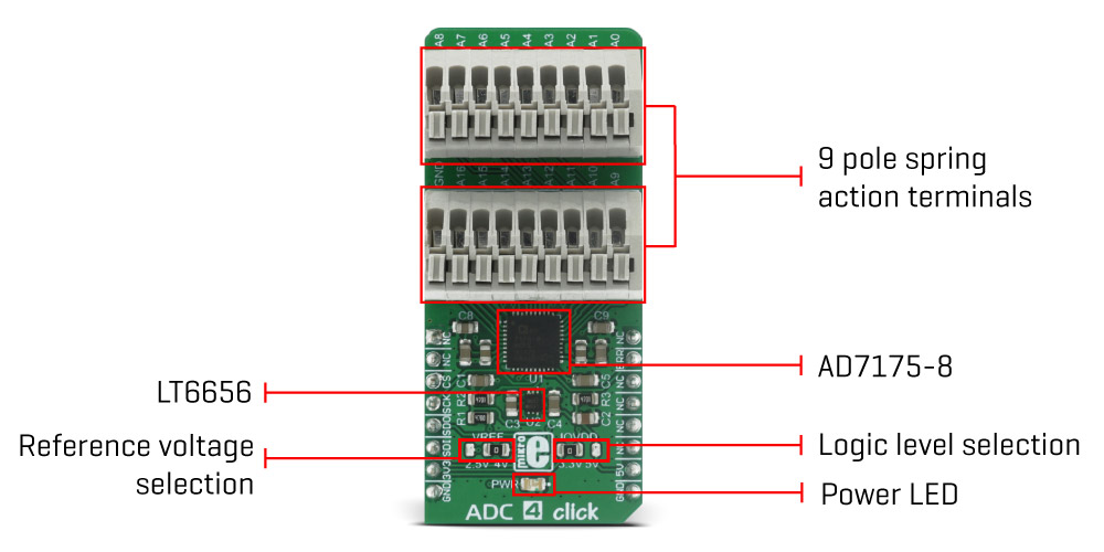
Along with the two 9 pole spring action terminals that provide easy and secure connection to the input channels, this device has many other outstanding features, which make it a perfect choice for an accurate and simple digitalisation of analog signals from various sensors in PLC/DCS modules, temperature and pressure measurement, medical and scientific instrumentation, chromatography and other similar applications, where accurate analog to digital conversion is needed.
How does it work?
The main active component of ADC 4 click is the AD7175-8 IC, a 24bit low noise, fast settling, multiplexed 8/16-channel sigma-delta analog-to-digital converter from Analog Devices. This integrated circuit allows for several different working modes and input connection configurations, giving a lot of flexibility to work with. Depending on the required precision, the ADC 4 click can work in 16bit or 24bit mode. It can use single-ended connections with one common pin or differential pair connections, allowing for any combination between the two types of inputs.
The AD7175-8 features analog and digital signal conditioning blocks and every channel can be individually set up to use them. Some of these features include several various kinds of filters (sinc3, sinc5 + sinc1, enhanced 50/60Hz filters), adjustable gain, offset and so on. Besides the 16 input channel registers, used to turn the channel off or on and select the differential pairs, there are also 8 "setups", consisted of four registers. Each setup contains one setup config register, one filter config register, one gain register and one offset register. These registers are used to adjust various conversion settings, such as the reference voltage source, filter type, the buffers on the input channels, the output sample rate, offset and gain for the channels and more. Although there are only 8 setups, the same setup can be applied on several input channels. This simplifies and speeds up the input channel configuration.
The input channels are connected to the ADC via the internal crosspoint multiplexer. This multiplexer is used to select the channel connected to the converter: if more than one input channel is enabled, the multiplexer will cycle through all of the enabled inputs automatically and will stop or continuously cycle through these channels, depending on the selected operational mode. It has a maximum channel scan rate of 50 kSPS (20 µs) on multiple channels, or 250 kSPS (20 µs) on a single channel for fully settled data.
The click board™ uses the SPI interface for the communication with the MCU. The MISO line of the mikroBUS™ is routed to the DOUT/RDY pin of the ADC, and besides for the SPI data output, it is also used as the indicator of the ready status of the sampled data: whenever the data is ready to be read, this pin is pulled low. More information about how to properly read data from the ADC can be found in the AD7175-8 datasheet. Also, MikroElektronika provides libraries that allow simple and easy reading of the data registers, as demonstrated in the provided demo application.
Besides the SPI lines, the #ERROR line is also routed to the INT pin of the mikroBUS™. The behavior of this pin can be set by the config register. In addition to being the #ERROR output, this pin can also be configured as the input pin, that can be used for stacking error signals from other devices. The error in this case is signalized by the appropriate bit in the status register. This pin can also be used as the GPIO, for some custom user defined function.
To further improve the sampling accuracy and reliability, the AD7175-8 IC features a temperature sensor. This sensor can be used to measure the ambient temperature. For example, if the ambient temperature is changed significantly, it is possible to invoke a recalibration routine, providing continous reliability over different temperature ranges. The temperature sensor can be selected the same way as any other channel, by the crosspoint multiplexer.
Besides the reference voltage provided by the AD7175-8's integrated LDO, an external LDO can also be used as a reference voltage source. It is the LT6656 from Linear Technology, a precise voltage regulator that provides low noise and low drop out voltage reference of 4.096V. By switching the position of the VREF SMD jumper, it is possible to change the external reference voltage applied to the REF+ pin of the ADC, between 2.5V and 4.096V. REF- pin is hardwired to the GND. The ADC can also use a custom voltage reference on the REF2+ and REF2- inputs, multiplexed with the AIN0 (A0) and AIN1 (A1) input pins. The values for the allowed REF2 voltage levels can be found in the ADC4 click electrical specifications table, below. Finally, the desired reference voltage source can be selected by setting the appropriate bits in the configuration registers of the AD7175-8.
The voltage level of the logic section can be selected via the IOVDD SMD jumper, between 3.3V and 5V. This allows for both 3.3V and 5V capable MCUs to use the SPI communication lines properly. The IOVDD is 3.3V by default but the device still requires 5V from the mikroBUS™ for a proper operation.
All of the input channels can be easily connected to the two 9 pole spring action block terminals, without having to use any additional tools, such as screwdrivers.
Specifications
| Type |
ADC |
| Applications |
Suitable for accurate and simple digitalization of the input voltage from the various sensors in PLC/DCS modules, temperature and pressure measurement, medical and scientific multichannel instrumentation, chromatography and more. |
| On-board modules |
AD7175-8 IC, a 24bit low noise, fast settling, multiplexed 8/16-channel sigma-delta analog-to-digital converter; LT6656 - LDO |
| Key Features |
It can sample inputs from 16 single-ended channels or 8 differential input channel pairs, sampling resolution of 24 bits and the output data rates can range from 5 SPS to 250 kSPS. |
| Interface |
GPIO,SPI |
| Input Voltage |
3.3V or 5V |
| Click board size |
L (57.15 x 25.4 mm) |
Pinout diagram
This table shows how the pinout on ADC 4 click corresponds to the pinout on the mikroBUS™ socket (the latter shown in the two middle columns).
| Notes | Pin |  | Pin | Notes |
|---|
|
NC |
1 |
AN |
PWM |
16 |
NC |
|
|
NC |
2 |
RST |
INT |
15 |
ERR |
Error signal |
| Chip Select |
CS |
3 |
CS |
RX |
14 |
NC |
|
| SPI Clock |
SCK |
4 |
SCK |
TX |
13 |
NC |
|
| SPI Data Output |
SDO |
5 |
MISO |
SCL |
12 |
NC |
|
| SPI Data Input |
SDI |
6 |
MOSI |
SDA |
11 |
NC |
|
| Power supply |
+3.3V |
7 |
3.3V |
5V |
10 |
+5V |
Power supply |
| Ground |
GND |
8 |
GND |
GND |
9 |
GND |
Ground |
ADC 4 click electrical specifications
| Description | Min | Typ | Max | Unit |
|---|
| Analog input voltage |
0 |
|
5 |
V |
| Output data rate |
5 |
|
250,000 |
SPS |
| Sampling bit depth |
16 |
|
24 |
bits |
| REF2+ voltage |
1 |
|
5 |
V |
| REF2- voltage |
0 |
|
4 |
V |
Onboard settings and indicators
| Label | Name | Default | Description |
|---|
| LD1 |
PWR |
- |
Power LED indicator
|
| JP1 |
VREF SEL |
Right |
Reference voltage selection. Defines input signal range, left position 2.5V, right 4.096V |
| JP2 |
IOVDD SEL |
Left |
Logic level selection, left position 3.3V, right 5V |
Software support
We provide a library for ADC 4 click on our LibStock page, as well as a demo application (example), developed using MikroElektronika compilers and mikroSDK. The provided click library is mikroSDK standard compliant. The demo application can run on all the main MikroElektronika development boards.
Library Description
Initializes and defines GPIO port driver and driver functions which are realized for communication via SPI bus and for calculating and converting analog signal to a digital one, according to the value of the referent voltage.
Key functions
uint8_t adc4_writeReg( const uint8_t regAddress, uint8_t *value );- This function writes data in the register determined by register address parameter of the function.
uint8_t adc4_readReg( const uint8_t regAddress, uint8_t *value );- This function reads data from the register determined by register address parameter of the function.
void adc4_reset(void);- This function reset ADC 4 click.
uint8_t adc4_getErrPin(void);- This function returns the value of INT (ERROR) pin which is controlled by ERR_DAT bit in the GPIOCON register.
void adc4_getConfig( const uint8_t regAddress, uint16_t *value );- This function writes the value of the configuration registers in storage determined by pointer value.
void adc4_setConfig( const uint8_t regAddress, uint16_t value );- This function writes a 16-bit value in the configuration registers determined by register address parameter.
uint32_t adc4_getData(void);- This function checks ready bit, is data ready or not, and returns 24-bit value from the data register.
uint16_t adc4_getVoltage(void);- This function returns 16-bit calculated value and AD converted voltage value.
Examples Description
The demo application is composed of three sections:
- System Initialization - Initializes GPIO pins (CS, INT), SPI module for communication with ADC 4 click and UART for data logging.
- Application Initialization - Initializes ADC 4 driver and sets up working mode.
- Application Task - (code snippet) - Sequential read of voltage. Information about the current voltage is logged to UART. Operation is repeated each second. Settings are set to calculate and convert input voltage in the range from -2.5V to 2.5V.
void applicationTask()
{
    voltage = adc4_getVoltage();

    IntToStr( voltage, text );
    mikrobus_logWrite( "Current Voltage : ", _LOG_TEXT );
    mikrobus_logWrite( text, _LOG_TEXT );
    mikrobus_logWrite( " mV", _LOG_LINE );

    Delay_ms( 1000 );
}
The full application code, and ready to use projects can be found on our LibStock page.
Other MikroElektronika libraries used in the example:
- Conversions
- C_String
- SPI
- UART
Additional notes and information
Depending on the development board you are using, you may need USB UART click, USB UART 2 click or RS232 click to connect to your PC, for development systems with no UART to USB interface available on the board. The terminal available in all MikroElektronika compilers, or any other terminal application of your choice, can be used to read the message.
mikroSDK
This click board is supported with mikroSDK - MikroElektronika Software Development Kit. To ensure proper operation of mikroSDK compliant click board demo applications, mikroSDK should be downloaded from the LibStock and installed for the compiler you are using.
For more information about mikroSDK, visit the official page.