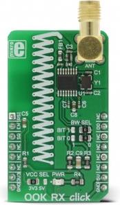
OOK RX click is a wireless receiver that operates at the frequency of 433MHz (sub-GHz). This device allows realization of a simple, low-speed wireless ad hoc communication network between a receiver and compatible transmitter. This device features an ASK/OOK demodulator, analog RSSI output, and integrated squelch capabilities.
This kind of networking is widely used for remote low-speed communication, such as the remote keyless access, remote fan or light control, garage or gate doors control, unidirectional low data rate wireless links and similar applications where this kind of communication is applicable.
How does it work?
OOK RX click uses the MICRF230 IC, a 400MHz to 450MHz ASK/OOK receiver with RSSI and squelch, from Microchip. The working principle of this device is based on decoding of information embedded in a radio signal. The ASK/OOK modulation is a way to encode information and assemble it into radio signals which can be transmitted and received wirelessly.
Generally, ASK is an abbreviate for the Amplitude Shift Key modulation, which is realized by shifting the amplitude of the signal, depending on the number that is going to be transmitted. For example, if the transmitted number is 1, the transmitted signal amplitude would be equal to the carrier signal amplitude, if the transmitted number is 2, the transmitted signal amplitude is as twice as the carrier signal amplitude and so on. The ASK method of modulation allows not only the binary communication, as more than two signal amplitudes can be detected by the receiver. However, this method is very susceptible to noise and interferences. To overcome this problem, an OOK modulation method was introduced.
The OOK modulation is very similar to the ASK, but it is of a binary type. OOK is an abbreviate for the Off-On Key, which perfectly describes this type of modulation. The presence of the carrier signal is recognized as the logical 1, while the absence of a carrier signal is recognized as the logical 0. This method is more immune to noise and interferences than the ASK modulation, and it allows for greater communication distance to be achieved.
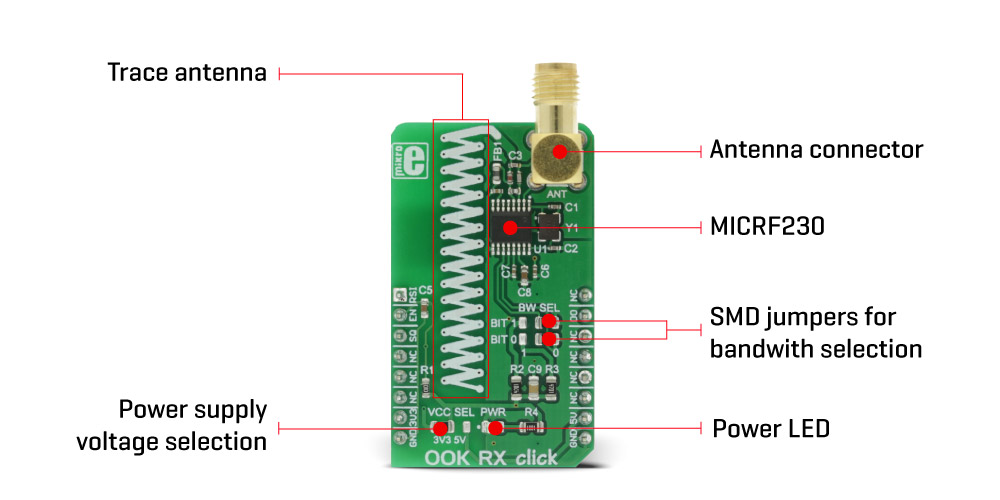
Signal demodulation starts with the RF signal being received and amplified by the low noise amplifier at the RF input. This signal is additionally processed by the internal mixers, filters and frequency synthesizers, and the processed intermediate frequency (IF) signal of about 330kHz is generated. This signal is passed to the decoding section. Decoder removes the carrier signal from the IF and filters the remaining baseband signal. This is done by a low pass filter with a user selectable bandwidth. The bandwidth choice is very important as it provides the optimal bit error rate (BER) for a specific data rate. Depending on the transmitted information data rate, users can select the bandwidth of the low pass filter, by moving the onboard SMD jumpers, labeled as BW SEL. These jumpers are used to set SEL0 and SEL1 pins of the IC to the proper logic levels, as you can see from the table given below.
Before the communication is attempted, the preamble burst should be received first. The preamble burst allows calibration to the receiving signal. When resuming from the Shutdown mode, the preamble should be long enough to allow the receiver to be fully awake and ready to receive data.
The integrated squelch function is used to limit the activity on the DO (data output) pin. This is particularly useful if the DO is used for an interrupt generation, as the squelch function will suppress any activity unless valid communication bits are detected. When the SQ pin is set to a logic LOW level, the squelch functionality is enabled, reducing random activity (noise) on the DO pin when there is no RF input signal. The SQ pin is pulled to a logic HIGH level internally, so it is disabled if the pin is left afloat. This pin is routed to the CS pin of the mikroBUS™.
Power consumption can be reduced if the device is put into the Shutdown mode. When EN pin is pulled high, the internal logic of the MICRF230 IC is activated. The EN pin is internally pulled LOW so that the device starts in the Shutdown mode when this pin is left afloat. The onboard capacitor ensures a proper power-up cycle since it will generate a small delay before the EN pin is pulled to a logic HIGH level, giving time to the power supply voltage to stabilize. The EN pin is routed to the mikroBUS™ RST pin.
OOK RX click has an RSSI (received signal strength indicator) output pin, used to directly measure the voltage level on the AGC (automatic gain compensation) section. The AGC is an integrated circuit section that provides a constant amplitude of the low pass filtered baseband signal. The voltage level on this pin determines the amplification of the AGC section. Since this level is not directly readable, an inverted, buffered version of the voltage is present on the RSSI pin, which can be directly used to determine the signal strength - which is inversely proportional to the signal amplification. The RSSI output pin has an impedance of 200? and it is routed to the AN pin of the mikroBUS™.
OOK RX click can work both with an integrated PCB trace antenna or a 433MHz external antenna, which can be attached to the onboard SMA connector of the click board, for improved range and received signal strength.
Both 3.3V and 5V operation is supported by this click board™. By moving the SMD jumper labeled as the VCC SEL, it is possible to select the operating voltage, so that both 3.3V and 5V capable MCUs can work with the OOK RX click board.
Specifications
| Type |
RF Sub 1GHz |
| Applications |
OOK RX click can be widely used for remote low-speed communication, such as the remote keyless access, remote fan or light control, garage or gate doors control, unidirectional low data rate wireless links, etc. |
| On-board modules |
MICRF230 IC, a 400MHz to 450MHz ASK/OOK receiver with RSSI and squelch, from Microchip |
| Key Features |
This device features an ASK/OOK demodulator, analog RSSI output, and integrated squelch capabilities. |
| Interface |
GPIO |
| Input Voltage |
3.3V or 5V |
| Click board size |
M (42.9 x 25.4 mm) |
Pinout diagram
This table shows how the pinout on OOK RX click corresponds to the pinout on the mikroBUS™ socket (the latter shown in the two middle columns).
| Notes | Pin |  | Pin | Notes |
|---|
| RSS Indication |
RSI |
1 |
AN |
PWM |
16 |
NC |
|
| Device enable |
EN |
2 |
RST |
INT |
15 |
DO |
Data Output |
| Squelching |
SQ |
3 |
CS |
RX |
14 |
NC |
|
|
NC |
4 |
SCK |
TX |
13 |
NC |
|
|
NC |
5 |
MISO |
SCL |
12 |
NC |
|
|
NC |
6 |
MOSI |
SDA |
11 |
NC |
|
| Power Supply |
3V3 |
7 |
3.3V |
5V |
10 |
5V |
Power Supply |
| Ground |
GND |
8 |
GND |
GND |
9 |
GND |
Ground |
OOK RX click electrical specifications
| Description | Min | Typ | Max | Unit |
|---|
| Receive modulation duty cycle |
20 |
|
80 |
% |
| Frequency range |
400 |
|
450 |
MHz |
Onboard settings and indicators
| Label | Name | Default | Description |
|---|
| LD1 |
PWR |
- |
Power LED indicator |
| JP1 |
PWR SEL |
Left |
Power supply voltage level selection: left position 3.3V, right 5V |
| JP2 |
BW SEL |
Right |
Output filter bandwidth select bit 0 (SEL0 pin) |
| JP3 |
BW SEL |
Right |
Output filter bandwidth select bit 1 (SEL1 pin) |
Filter corner frequencies depending on jumper configuration are given in table:
| BW SEL (BIT 1) | BW SEL (BIT 0) | Low-Pass Filter BW | Maximum Encoded Bit Rate |
|---|
| 0 |
0 |
1625 |
2.5KBps |
| 0 |
1 |
3250 |
5KBps |
| 1 |
0 |
6500 |
10KBps |
| 1 |
1 |
13000 |
20KBps |
Software support
We provide a library for OOK RX click on our LibStock page, as well as a demo application (example), developed using MikroElektronika compilers and mikroSDK. The provided click library is mikroSDK standard compliant. The demo application can run on all the main MikroElektronika development boards.
Library description
This library contains a function that receives data from OOK RX click.
Key functions
uint8_t ookrx_receiveData(uint16_t startPacket, uint8_t * pReceivedData, uint8_t numBytes)- Reads data from the DO pin.
The application is composed of three sections :
- System Initialization - Initializes pin directions and logger utility.
- Application Initialization - Initializes driver.
- Application Task (Code Snippet) - Prints out any received data via UART.
void applicationTask()
{
    char outputTxt[20];
    uint8_t receivedPacket[1];

    if(!(ookrx_receiveData(0xCE35, &receivedPacket, 1)))
    {
        ShortToStr(receivedPacket[0], outputTxt);
        mikrobus_logWrite(outputTxt, _LOG_LINE);
    }
}
The full application code, and ready to use projects can be found on our LibStock page.
MikroElektronika Libraries used in the example:
- UART
- Conversions
- C_String
Additional notes and information
Depending on the development board you are using, you may need USB UART click, USB UART 2 click or RS232 click to connect to your PC, for development systems with no UART to USB interface available on the board. The terminal available in all MikroElektronika compilers, or any other terminal application of your choice, can be used to read the message.
mikroSDK
This click board is supported with mikroSDK - MikroElektronika Software Development Kit. To ensure proper operation of mikroSDK compliant click board demo applications, mikroSDK should be downloaded from the LibStock and installed for the compiler you are using.
For more information about mikroSDK, visit the official page.