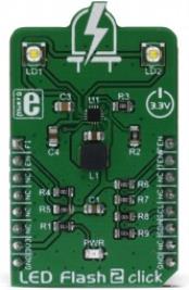
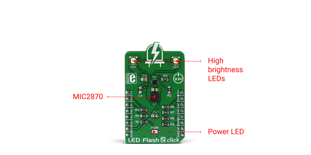
LED Flash 2 click is a powerful flash/torch click, featuring the MIC2870 from Microchip, a high-efficiency flash LED driver, optimized for driving one or two high-brightness camera flash LEDs. The MIC2870 IC can drive one high brightness LED up to 1.5A or two high brightness LEDs, up to 750mA each. Two high brightness LEDs are already mounted on the Led Flash 2 click, so the click board is ready to be used right away.
LED Flash 2 click provides two modes of operation - the Torch mode and the Flash mode. While working in Torch mode, the output current is adjusted so that the continuous operation of the LEDs is provided. When it is set to work in the Flash mode, the LED current is maximized and while giving a powerful light, it can not work for prolonged periods. The Torch mode will turn the click board™ into a simple handheld torchlight, while the Flash mode is good for using the LEDs as the camera flash, providing good images in various low light situations.
How does it work?
The main active part of this click board™ is the MIC2870, a synchronous boost flash LED driver, which can be set to work in a Flash or Torch mode. It uses integrated inductive boost converter with 2 MHz switching frequency, which allows the use of a very small inductor and output capacitor. The operating mode can be set both with the dedicated pins and the I2C interface commands. The I2C interface is quite fast and it can operate up to 3.4 MHz. The I2C clock speed ensures fast communication and therefore minimal response time. This is a very important feature when used as a flashlight for the camera applications, where an instant reaction is needed.
The click board comes equipped with the two XPCWHT-L1-R250, high brighness LED elements by Cree, Inc.
When working in the Flash mode, the current through the single LED channel is maximized and determined by the resistors, connected to the FRSET input of the MIC2870 IC. On the Led Flash 2 click, the maximum current is set by the 10K resistor, to 750mA per LED channel. This current can be additionally limited by selecting the desired flash current level percentage in the flash control register (01h).
The flash safety timeout feature automatically shuts down the flash current, if the flash mode is enabled for an extended period of time. The timeout can be set by the corresponding bits in the flash control register (01h). For more information about the available registers and their values, consult the MIC2870 datasheet.
Flash inhibition pin, or the FI pin - routed to the mikroBUS™ AN pin, with the corresponding bit in the Torch control register (02h), is used to limit the Flash mode current value to the Torch mode current value. This will effectively override the Flash mode.
For the Torch mode operation, the current is set to a lower value than for the Flash mode - with the 10K resistor connected to the TRSET, this current is set to 187.5mA. Similar as for the Flash mode, the torch control register (02h) controls the percentage of the current, set by the TRSET resistor.
Rising edge on the TEN or FEN - routed to the mikroBUS™ INT and PWM pins, will activate the Torch mode or the Flash mode, respectively. These modes can also be activated by setting the corresponding bits in the control registers.
EN pin - routed to the mikroBUS™ RST pin, along with the corresponding bit in the status register (00h), is used to enable the MIC2870 IC. Setting this pin to a HIGH logic level will put the IC into the standby state. Driving this pin low for more than 1 second - or setting the bit to a low state will put the MIC2870 IC into a shutdown mode, the lowest power consumption mode for this click board™.
All the control pins are internally pulled to a LOW logic state, so there is no need to use any pull-down resistors for this purpose, which further simplifies application designs with this click board™.
Specifications
| Type |
Flash |
| Applications |
Flash or torch light for various hand-held devices, such as the small camera light or a cell phone flashlight. It can be also used as a signal light, bicycle light, car taillight, etc. |
| On-board modules |
MIC2870 - synchronous boost flash LED driver from Microchip |
| Key Features |
High efficiency LED driver operating in two modes - Flash and Torch. Drives two high brightness LEDs with up to 750mA, short circuit and open circuit detection on the output, easy to use via the dedicated pins or ultra fast I2C interface, up to 3.4MHz. |
| Interface |
GPIO,I2C |
| Input Voltage |
3.3V |
| Click board size |
M (42.9 x 25.4 mm) |
Pinout diagram
This table shows how the pinout on LED Flash 2 click corresponds to the pinout on the mikroBUS™ socket (the latter shown in the two middle columns).
| Notes | Pin |  | Pin | Notes |
|---|
| Flash inhibit |
FI |
1 |
AN |
PWM |
16 |
FEN |
Flash enable |
| Chip enable |
EN |
2 |
RST |
INT |
15 |
TEN |
Torch enable |
|
|
3 |
CS |
RX |
14 |
NC |
|
|
|
4 |
SCK |
TX |
13 |
NC |
|
|
|
5 |
MISO |
SCL |
12 |
SCL |
I2C clock |
|
|
6 |
MOSI |
SDA |
11 |
SDA |
I2C data |
| Power supply |
+3.3V |
7 |
3.3V |
5V |
10 |
NC |
|
| Ground |
GND |
8 |
GND |
GND |
9 |
GND |
Ground |
LED Flash 2 click electrical specifications
| Description | Min | Typ | Max | Unit |
|---|
| Switching frequency |
1.8 |
2.0 |
2.2 |
MHz |
| I2C frequency |
|
|
3.4 |
MHz |
| LED current per channel |
0 |
|
750 |
mA |
Onboard settings and indicators
| Label | Name | Default | Description |
|---|
| LD1 |
Flash LED 1 |
- |
High Brightness LED |
| LD2 |
Flash LED 2 |
- |
High Brightness LED |
| PWR |
Power LED |
- |
Power LED indicator |
Software support
We provide a library for the LED Flash 2 click on our LibStock page, as well as a demo application (example), developed using MikroElektronika compilers. The demo can run on all the main MikroElektronika development boards.
Library Description
Library for LED Flash 2 click contains generic read / write functions. The library also contains control function (setMode), that can set click into any of the possible modes of operation, as well as a function that can toggle Flash inhibit pin on/off.
Besides the mode parameter used to set the working mode of the click, the LED current is also forwarded to the functions as the parameter by means of constants, that are named according to the percentage of the current they are used to set - e.g. _LEDFLASH2_CUR_100 will not scale down the current and it will be 100% of what is set by the current limiting resistors on the click board. When using the FLASH mode (_LEDFLASH2_MODE_FLASH), another function parameter (_LEDFLASH2_FTMR_312) is used and it represents the safety timer, after which the LEDs will get turned off, to prevent damage. Otherwise it can be set to 0.
Key functions
uint8_t ledflash2_readRegister(uint8_t regAddress) - Generic read register function
void ledflash2_writeRegister(uint8_t regAddress, uint8_t regData) - Generic write register function
ledflash2_setMode(_LEDFLASH2_MODE_FLASH, _LEDFLASH2_CUR_100, _LEDFLASH2_FTMR_312);- Sets the operation mode
void ledflash2_toggleFlashInhibit(uint8_t pinState) - Toggles the Flash inhibit pin on/off
Examples description
The application is composed of three sections:
-
System Initialization - Initializes pins, I2C peripheral, and logger.
-
Application Initialization - Initializes driver, and sets the click into "OFF"
-
Application Task - (Code snippet) This function will demonstrate how to use the flash mode, and the torch mode, with different power settings. It will then turn the click off
IMPORTANT NOTE: LED lights can be very bright, even with the lowest power settings. Avoid looking directly into the light, when working with the click.
    Delay_ms(1000);
    mikrobus_logWrite("Do not look directly into the led lights.", _LOG_LINE);
    mikrobus_logWrite("Triggering flash in 5...", _LOG_LINE);
    Delay_ms(1000);
    mikrobus_logWrite("4...", _LOG_LINE);
    Delay_ms(1000);
    mikrobus_logWrite("3...", _LOG_LINE);
    Delay_ms(1000);
    mikrobus_logWrite("2...", _LOG_LINE);
    Delay_ms(1000);
    mikrobus_logWrite("1...", _LOG_LINE);
    Delay_ms(1000);
    mikrobus_logWrite("Cheese!", _LOG_LINE);

    ledflash2_setMode(_LEDFLASH2_MODE_FLASH, _LEDFLASH2_CUR_100, _LEDFLASH2_FTMR_312);

    Delay_ms(350);
    ledflash2_setMode(_LEDFLASH2_MODE_OFF, 0, 0);
    Delay_ms(2000);
    mikrobus_logWrite("Switching to the torch mode in a moment...", _LOG_LINE);
    Delay_ms(2000);
    ledflash2_setMode(_LEDFLASH2_MODE_TORCH, _LEDFLASH2_CUR_100, 0);
    Delay_ms(5000);
    mikrobus_logWrite("Dimming the torch light...", _LOG_LINE);
    ledflash2_setMode(_LEDFLASH2_MODE_TORCH, _LEDFLASH2_CUR_18, 0);
    Delay_ms(5000);
    mikrobus_logWrite("Switching off...", _LOG_LINE);
    ledflash2_setMode(_LEDFLASH2_MODE_OFF, 0, 0);
The full application code and ready to use projects can be found on our LibStock page.
Other mikroE Libraries used in the example:
Additional notes and information
Depending on the development board you are using, you may need USB UART click, USB UART 2 click or RS232 click to connect to your PC, for development systems with no UART to USB interface available on the board. The terminal available in all MikroElektronika compilers, or any other terminal application of your choice, can be used to read the message.