Featuring highly programmable and adoptable AFE IC, this Click board™ can be used in a really wide range of different applications. It allows development of oximetry algorithms, development of heart rate measurement applications, even building of ambient light projects. Offering expandability with external LED and PD elements, this Click board™ can be used in virtually any photometric application.
Pulse oximetry or SpO2
Oxygen saturation in the blood can be determined by measuring the light absorption in the red/IR part of the spectrum. The oxygen saturated blood absorbs more red light and less infrared, than the unsaturated blood. This fact can be used to determine the oxygen saturation of the blood. For a healthy adult person, the peripheral capillary oxygen saturation (SpO2) percentage ranges from 95% to 100%. Oximeter click can provide the SpO2 measurement, by simply placing the index finger over the optical sensor.
How does it work?
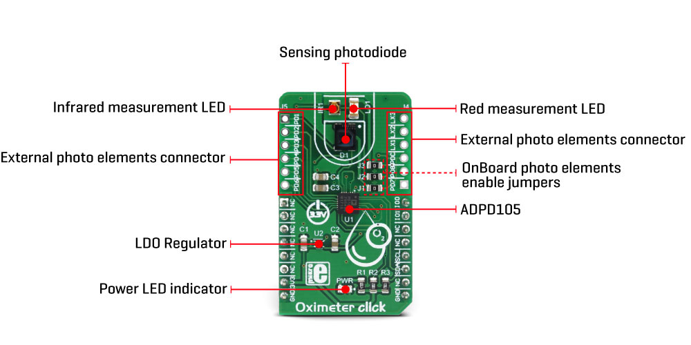
The main component of the Oximeter click is the ADPD105, a highly configurable photometric front end (AFE) device from Analog Devices. This IC has three current sinks LED drivers with the common cathode and four AFE input channels to which the photodiode (PD) elements can be connected. The IC actually has eight PD inputs, which can be routed to AFE input channels, depending on needs. There are three possible PD configuration settings, programmable via the I2C interface. Oximeter click uses two LEDs, well suited for measuring the oxygen saturation in the blood: a red color LED and an infrared LED. Also, a single PD element is used to sense the reflected light. However, this click offers headers on its sides, which allow connecting of additional LED/PD elements, expanding the usability of the Click board™. Jumpers labeled as J1 to J3 are used to completely disconnect the onboard photo elements, freeing these lines to be used with the external photo elements.
The current from PDs passes through the analog block. The analog block itself contains four AFE signal conditioning sections, which process the input current by using transimpedance amplifiers (TIA) with programmable gain, bandpass filters, and integrators, reducing the influence of external factors - such as the ambient light and similar. The analog block is coupled with the 14-bit ADC, and finally - a digital data path and control block used to manage all the internal routing and provide data on the I2C interface.
The main working principle of this device is based on driving LED elements and measuring the response via the photosensors. There are two time-slots that are consecutively executed, each with its own path that uses independent settings for LED driving, AFE setup, and data collection. During each time-slot period, the configured LEDs (or a LED) are pulsed with programmable magnitude, duration and number of pulses. The PD sensing intervals coincidence with the LED pulses, rejecting ambient light and other external influences that way. Each LED pulse response is converted by the 14-bit ADC, and integrated by the AFE integrator block. Up to 255 pulse responses can be integrated during one sampling period, providing up to a 20-bit maximum range.
An important thing when performing the measurement is to offset the AFE integration the right way: if the AFE integration window is not offset correctly, or its size is too small or too large, either the LED pulse will be skipped completely, or too much noise will affect the integration. Ideally, a LED pulse should be captured by the AFE integration window that matches its position and size. Datasheet of the ADPD105 device describes methods how to set the AFE integration window correctly, especially when used with custom LEDs and PDs.
The time-slot feature, and using two different LED/PD settings are utilized on the Click board™ to provide two different measurements in a sequence - one for the red LED, one for the IR LED. By comparing these two measurements, it is possible to determine blood oxygen saturation.
After the measurement is completed, the data is available either in the register directly, or it is stored on the 128-byte FIFO memory buffer. The interrupt event can be used to alert the host MCU when the FIFO buffer exceeds the programmed threshold. Both time slots are able to store their data on the FIFO buffer.
Two GPIO (I/O) pins can be configured in a number of different ways: they can be set as interrupts, with programmable polarity, driving mode (open-drain, push-pull), and functionality. They can serve as interrupt outputs, or alternatively, they can be set to output 32kHz clock, to accept external clock, sampling synchronization pulses, etc. These pins perfectly fit in the programmable concept of the ADPD105 IC itself, offering the extended functionality of the Click board™. IO0 and IO1 pins are routed to the PWM pin of the mikroBUS™ and to the INT pin of the mikroBUS™, respectively.
Already low power consumption can be further reduced by disabling all the unused channels. This will free the resources, and reduce power consumption. The IC requires 1.8V in order to work properly. Therefore, a small regulating LDO is used, providing 1.8V out of 3.3V mikroBUS™ rail.
More information about the registers and how to set them can be found in the ADPD105 IC datasheet. However, included library contains functions that allow easy configuration and use of the Oximeter click. The included exemplary (demo) application demonstrates their functionality and can be used as a reference for a custom design.
Specifications
| Type |
Biomedical |
| Applications |
Can be used for development of oximetry algorithms, heart rate measurement applications, ambient light applications... Offering expandability with external LED and PD elements, this Click board™ can be used in virtually any photometric application. |
| On-board modules |
ADPD105, a highly configurable photometric front end (AFE) device from Analog Devices |
| Key Features |
Highly programmable photometric AFE device from Analog Devices, external headers for additional photo elements, onboard LEDs and photodiode optimized for the oximetry measurements |
| Interface |
I2C |
| Input Voltage |
3.3V |
| Click board size |
M (42.9 x 25.4 mm) |
Pinout diagram
This table shows how the pinout on Oximeter click corresponds to the pinout on the mikroBUS™ socket (the latter shown in the two middle columns).
| Notes | Pin |  | Pin | Notes |
|---|
|
NC |
1 |
AN |
PWM |
16 |
IO0 |
Interrupt/GPIO 0 |
|
NC |
2 |
RST |
INT |
15 |
IO1 |
Interrupt/GPIO 1 |
|
NC |
3 |
CS |
RX |
14 |
NC |
|
|
NC |
4 |
SCK |
TX |
13 |
NC |
|
|
NC |
5 |
MISO |
SCL |
12 |
SCL |
I2C Clock |
|
NC |
6 |
MOSI |
SDA |
11 |
SDA |
I2C Data |
| Power supply |
3.3V |
7 |
3.3V |
5V |
10 |
NC |
|
| Ground |
GND |
8 |
GND |
GND |
9 |
GND |
Ground |
Onboard jumpers and settings
| Label | Name | Default | Description |
|---|
| LD1 |
PWR |
- |
Power LED indicator |
| J1 |
J1 |
Populated |
PD1 onboard photodiode enable: populated - PD enabled, unpopulated - PD disabled |
| J2 |
J2 |
Populated |
LEDX2 onboard IR LED enable: populated - LED connected, unpopulated - LED disconnected |
| J3 |
J3 |
Populated |
LEDX1 onboard red LED enable: populated - LED connected, unpopulated - LED disconnected |
| J4 |
J4 |
- |
External photo elements connection header 1 |
| J5 |
J5 |
- |
External photo elements connection header 2 |
Note: when using external photo elements on lines LEDX1, LEDX2, and PD1, it is necessary to remove the respective jumpers (J1 - J3)
Software support
We provide a library for the Oximeter Click on our LibStock page, as well as a demo application (example), developed using MikroElektronika compilers. The demo can run on all the main MikroElektronika development boards.
Library Description
The library can communicate with the device via I2C driver by writing to the registers and by reading from the registers, including data registers. The library has the ability to measure the level of oxygen (O2) in the blood, something like blood pressure. Library also can configure the device to works in two Time Slot Mode independently with different configurations. For more details check the documentation.
Key functions:
uint8_t oxim_writeReg( uint8_t register_address, uint16_t transfer_data ) - The function writes 16-bit data to the register.uint8_t oxim_setTimeSlotA( uint8_t enableSlotA, uint8_t enablePhotodiode, uint8_t enableLED, uint8_t setMode ) - The function performs the configuration for Time Slot A and enables the interrupt for this Slot.uint8_t oxim_enableChannels( uint8_t selectChannel ) - The function determines which channel/channels be enabled.void oxim_readData( uint32_t *channResults, uint8_t resultMode ) - The function reads data in the desired mode for determined Slot.
Example description
The application is composed of three sections :
- System Initialization - Initializes peripherals and pins.
- Application Initialization - Initializes I2C driver and performs the device configuration which puts Time Slot Ain enabled mode and LEDX2 (IR diode) to the active state. On Oximeter click the photodiode is connected on PD1 input, and because we will observe the Channel 1 in this example (CH1 is enabled). Before the device configuration, the SW reset will be performed and in this way, we will put the registers in the initial state.
- Application Task - (code snippet) - Gets data when IR diode (LEDX2) is enabled, and after that gets data when LED diode(LEDX1) is enabled. Repeats operation 10 times and then calculates the average value for both results. The results are sent to the serial port, to be displayed as a graph by the application. Note: For this example, you must have the serial plot application. The IR diode is internally connected on LEDX2 input, and the LED diode is internally connected on LEDX1 input. The photodiode is internally connected on PD1 input. When we want to perform some register configuration we must first put the device in Program Operating Mode, then we can set the desired register to the desired value, and when we finished, then we can put the device back to the Normal Operating Mode.
void applicationTask()
{
 oxim_plotDisplay();
}
Additional Functions :
- void oxim_plotDisplay() - Makes the average value of 10 samples when IR diode and LED diode is enabled alternately and logs results on the serial port in a form of a graph.
- void oxim_uartDisplay() - Gets 100 samples of data when IR diode is enabled, and then gets 100 samples of data when LED diode is enabled and after that logs this 100 samples of data for both diode parallel on USB UART as graphics view.
- void oxim_logsResults() - Gets data which is determined in application init configuration and logs result on USB UART.
The full application code, and ready to use projects can be found on our LibStock page.
Other mikroE Libraries used in the example:
Additional notes and information
Depending on the development board you are using, you may need USB UART click, USB UART 2 click or RS232 click to connect to your PC, for development systems with no UART to USB interface available on the board. The terminal available in all MikroElektronika compilers, or any other terminal application of your choice, can be used to read the message.
mikroSDK
This click board is supported with mikroSDK - MikroElektronika Software Development Kit. To ensure proper operation of mikroSDK compliant click board demo applications, mikroSDK should be downloaded from the LibStock and installed for the compiler you are using.
For more information about mikroSDK, visit the official page.
LEDX2 onboard IR LED enable: populated - LED connected, unpopulated - LED disconnected