RS-232 standard was introduced in '60, as a serial interface between Data Terminal Equipment (DTE) and Data Communication Equipment (DCE). After undergoing several revisions, it is still used, even 60 years after it has been first introduced. It gained popularity due to the fact that it was an integral part of personal computer motherboards for quite a long time, but also for its robustness. However, due to many inherent limitations, it is replaced by a much faster and more compact USB interface. Still, there are some devices that use RS-232 communication. This Click board™ is a perfect solution for battery powered hand-held and portable equipment, PDAs, palmtops, digital cameras, and other devices that still support the RS-232 standard, allowing them to communicate with any embedded application over the SPI or I2C interface, offering ESD protection for the host MCU.
How does it work?
The design of the UART I2C/SPI click is based around two integrated circuits. The first IC is the SC16IS740, an I2C/SPI to UART interface, 64 bytes of transmit and receive FIFOs, and IrDA SIR built-in support, from NXP. This IC bridges the data communication between the two interfaces, offering many additional features, such as the support for the automatic hardware and software flow control, RS-485 support and software reset of the UART. The SC16IS740 can be configured over the SPI or I2C interface, by writing values to a 16C450 compatible set of registers. Maintaining the backward compatibility with the widely popular 16C450 asynchronous communications element (ACE). This allows the software to be easily written or ported from another platform.

The second IC provides a physical level conversion for RS-232 communication, as well as the ESD protection within the range of ±15kV. Since the SC16IS740 operates using only TTL/CMOS logic levels, another IC had to be used in order to provide a proper signal conversion on a hardware level. The voltage level of the RS-232 signal can vary between -15V and +15V (-3V to -15V when the line is de-asserted and +3V to +15V when asserted). The MAX3237 IC, a low-power, true RS-232 transceiver from Maxim Integrated is used for the purpose of conditioning the CMOS/TTL level UART signal from the SC16IS740, into a proper RS-232 signal. All UART lines are driven through this IC, including RXD, TXD, CTS, and RTS lines. After being translated to RS-232 signal levels, these signals are available over the standard RS232 connector (DE-9).
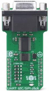
The Click board™ is equipped with a number of SMD jumpers. There are five jumpers grouped under the COMM SEL label, used to select one of two available interfaces: SPI, and I2C. By moving all the jumpers at the desired position, the user can select the interface used for the communication with the host MCU. It is advisable to move all the jumpers at once to either left (SPI) or the right (I2C) position.
The #RESET pin performs the hardware reset of the SC16IS740 IC. Besides the hardware reset, this device also supports the software reset, by writing a value into the SRESET register. After the Power ON reset, or after a reset pulse is sent over the #RESET pin, it is advised to wait for the external clock oscillator to stabilize. The provided external clock oscillator operates at 1.8432 MHz and takes up to 3ms to stabilize. The #RESET pin is routed to the mikroBUS™ RST pin and it is active LOW.
The #INT allows the host MCU to receive an interrupt from the SC16IS740 IC. This pin allows seven different interrupt sources to generate an interrupt signal. This allows more optimized software (firmware) to be written, as the host MCU does not have to continuously poll the LSR register to see if any interrupt needs to be serviced. However, the software does not have to use interrupts, since each of the interrupt sources will be indicated within the Line Status Register (LSR).
The A0/#CS line has two purposes: when the SC16IS740 IC is used in the SPI mode, this pin performs the usual SPI Chip Select function. When used during the I2C mode, this pin determines the I2C address of the device. Therefore, the I2C address of the SC16IS740 IC can be easily changed by applying the specific logic level to this pin.
The datasheet of the SC16IS740 offers more information about using and configuring the SC16IS740 IC. However, the Click board™ is supported by a mikroSDK library, offering functions that simplify the prototyping and firmware development.
This Click board™ is operated by 3.3V only. To be able to use it with MCUs that use 5V logic level on their communication lines, a proper level-translation circuit should be used.
Specifications
| Type |
RS232 |
| Applications |
This Click board™ is a perfect solution for battery powered hand-held and portable equipment, PDAs, palmtops, digital cameras, and other devices that still support the RS-232 standard, allowing them to communicate with any embedded application over the SPI or I2C interface, while offering ESD protection. |
| On-board modules |
SC16IS740, an I2C/SPI to UART interface, 64 bytes of transmit and receive FIFOs, and IrDA SIR built-in support, from NXP; MAX3237 IC, a low-power, true RS-232 transceiver, from Maxim Integrated |
| Key Features |
It supports both I2C and SPI interfaces, bridging them to UART, supports a lot of other features including Line-Break generation and detection, programmable special character detection, auto flow control (software and hardware), 15kV ESD protection, onboard RS-232 connector, etc. |
| Interface |
I2C,SPI |
| Input Voltage |
3.3V |
| Click board size |
L (57.15 x 25.4 mm) |
Pinout diagram
This table shows how the pinout on UART I2C/SPI Click corresponds to the pinout on the mikroBUS™ socket (the latter shown in the two middle columns).
| Notes |
Pin |
 |
Pin |
Notes |
|---|
| |
NC |
1 |
AN |
PWM |
16 |
NC |
|
| Reset |
RST |
2 |
RST |
INT |
15 |
INT |
Interrupt |
| Chip Select / A0 |
CS |
3 |
CS |
RX |
14 |
NC |
|
| SPI Clock |
SCK |
4 |
SCK |
TX |
13 |
NC |
|
| SPI Data OUT |
SDO |
5 |
MISO |
SCL |
12 |
SCL |
I2C Clock |
| SPI Data IN |
SDI |
6 |
MOSI |
SDA |
11 |
SDA |
I2C Data |
| Power Supply |
3V3 |
7 |
3.3V |
5V |
10 |
NC |
|
| Ground |
GND |
8 |
GND |
GND |
9 |
GND |
Ground |
Onboard settings and indicators
| Label |
Name |
Default |
Description |
|---|
| LD1 |
PWR |
- |
Power LED indicator |
| JP1 - JP5 |
COMM SEL |
Left |
Communication interface selection: left position SPI, right position I2C |
Software support
We provide a library for the UART I2C/SPI Click on our LibStock page, as well as a demo application (example), developed using MikroElektronika compilers. The demo can run on all the main MikroElektronika development boards.
Library Description
Library contains basinc functions for working with the click board.
Key functions:
void uarti2cspi_init(uint16_t baud) - Function for initializing the click board.uint8_t uarti2cspi_uartRead() - Function for reading a character.void uarti2cspi_uartWrite(uint8_t wByte) - Fucntion for writing a character.
Examples description
The application is composed of the three sections :
- System Initialization - Initialize the GPIO and communication structures.
- Application Initialization - Initialize the communication interface and configure the click board.
- Application Task - Character data is sent trough the UART interface of the click board. When all of the data has been sent the echo example is started.
void applicationTask()
{
    uint16_t counter_var;
    char text[5];


    for(counter_var=0;counter_var<10;counter_var++)
    {
        WordToStr(counter_var,&text[0]);
        Ltrim(&text[0]);
        uarti2cspi_serialWrite(&text[0],_LINE_PRINT);
    }

    uarti2cspi_serialWrite(&str1[0],_LINE_PRINT);
    uarti2cspi_serialWrite(&str2[0],_LINE_PRINT);
    uarti2cspi_uartWrite(0x00);

    while(1)
    {
        uarti2cspi_uartWrite(uarti2cspi_uartRead());
    }
}
Additional Functions :
All additional functions such as timer initialization and default handler.
The full application code, and ready to use projects can be found on our LibStock page.
Other mikroE Libraries used in the example:
ConversionsC_StringSPII2CUART
Additional notes and informations
Depending on the development board you are using, you may need USB UART click, USB UART 2 click or RS232 click to connect to your PC, for development systems with no UART to USB interface available on the board. The terminal available in all MikroElektronika compilers, or any other terminal application of your choice, can be used to read the message.
mikroSDK
This click board is supported with mikroSDK - MikroElektronika Software Development Kit. To ensure proper operation of mikroSDK compliant click board demo applications, mikroSDK should be downloaded from the LibStock and installed for the compiler you are using.
For more information about mikroSDK, visit the official page.