The button used on the Button Y click meets all the menitoned requirements. It is a reliable and endurable tactile switch, with a reasonably large button surface of 6.7mm in diameter. Very low typical bouncing time of less than 1.5ms, extremely low ON resistance of less than 100m?, and an embedded yellow LED with the adjustable brightness are features that make the Button Y click very appealing tactile switch solution, which can be used in many different low power electronic applications, such as various control boards, user input keys, activators of certain functions with built-in signalization, etc.
How does it work?
Button Y click is equipped with the high-quality, single-pole, single-throw (SPST) tactile switch labeled as 3006.2111, produced by Marquardt. This is a high-quality, low-profile pushbutton with a reasonably large diameter of 6.8mm. It is equipped with a yellow LED, which can be dimmed by applying a PWM signal from the MCU. Therefore, the anode of the LED is connected to the PWM pin of the mikroBUS™. The embedded LED can be used for a signalization, but also for aesthetic purposes.

The switch itself has very good characteristics: it has a low ON resistance (a resistance through the button while it is pressed) of less than 100m?, very low bouncing time (a time during which the contact plates settle down) of less than 1.5ms typically. The mechanical endurance of the tactile switch is rated to more than 500,000 cycles, while applying 14VDC, 10mA. The total travel distance of the button is 2.9 mm, while the tactile force of the button is 4N. The maximum voltage that should be used between the switch terminals is 28V, while the current should stay below 50mA.
Two important properties that describe a button, are its mechanical endurance and bouncing delay. Those two attributes depend on each other, so when a significant bouncing appears, it might be a sign of a switch deterioration. Likewise, a switch will develop larger bouncing effect as it is been used over time. The mechanical endurance is also affected by the force applied to the switch while operated, as well as its eccentricity (pressing the button off center).
Bouncing time is a parameter which describes how fast contact plates of a switch are settled down. Each material has some elastic properties. This is also true for the contact plates of the button. Different types of switches have different mechanism to establish a contact, but they are all based on a common principle: they are made so they accumulate the pressure force, until there is enough energy stored so that the plate can be actuated very fast, turning the accumulated pressure into kinetic energy (resulting with the familiar click sound). The most often, a form of spring mechanism is used. However, when hitting the second, fixed plate, a moving plate will bounce off a few times, depending on the elasticity of the system, its speed and so on. There is no ideal dampening mechanism to reduce the bouncing completely. This button will accumulate force up to about 1N before its actuated, providing a tactile feedback while clicking.
The tactile switch used on Button Y click has an excellent bouncing duration of less than 1ms. However small, the bouncing of a button needs to be compensated, either in the application firmware, or the hardware. Button Y click has a simple debouncing circuit, made of a 10k? resistor and 10nF capacitor, which is sufficient for the most cases. The debounced signal will have a small delay, depending on a dampening circuitry. The delay is in the range of a few milliseconds, which is far less than a human can sense. Finally, the button is intended to be operated by a human, so even much larger delay is perfectly acceptable for this type of device.
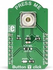
The button is active HIGH, which means that when it is pressed, a HIGH logic level will be applied to the INT pin. This switch will be pulled to a LOW logic level by the 10k? pull-down resistor while inactive, preventing the input pin of the MCU to become floating. The switch signal is routed to the INT pin of the mikroBUS™. An onboard SMD jumper labeled as VCC SEL is used to set the voltage for the HIGH logic level, allowing the Button Y click to be used with a wide range of different MCUs.
Specifications
| Type |
Button |
| Applications |
Button Y click very appealing tactile switch solution, which can be used in many different low power electronic applications, such as various control boards, user input keys, activators of certain functions with built-in signalization, etc. |
| On-board modules |
3006.2111, a high-quality SPST tactile switch, produced by Marquardt |
| Key Features |
Excellent mechanical endurance, integrated yellow LED with the adjustable brightness, very low ON resistance, comes equipped with the debouncing circuit |
| Interface |
GPIO,PWM |
| Input Voltage |
3.3V or 5V |
| Click board size |
M (42.9 x 25.4 mm) |
Pinout diagram
This table shows how the pinout on Button Y Click corresponds to the pinout on the mikroBUS™ socket (the latter shown in the two middle columns).
| Notes |
Pin |
 |
Pin |
Notes |
|---|
| |
NC |
1 |
AN |
PWM |
16 |
PWM |
LED intensity |
| |
NC |
2 |
RST |
INT |
15 |
INT |
Switch OUT |
| |
NC |
3 |
CS |
RX |
14 |
NC |
|
| |
NC |
4 |
SCK |
TX |
13 |
NC |
|
| |
NC |
5 |
MISO |
SCL |
12 |
NC |
|
| |
NC |
6 |
MOSI |
SDA |
11 |
NC |
|
| Power supply |
3V3 |
7 |
3.3V |
5V |
10 |
5V |
Power Supply |
| Ground |
GND |
8 |
GND |
GND |
9 |
GND |
Ground |
Onboard settings and indicators
| Label |
Name |
Default |
Description |
|---|
| PWR |
PWR |
- |
Power LED indicator |
| JP1 |
VCC SEL |
Left |
Logic voltage level selection: left position 3.3V, right position 5V |
Software support
We provide a library for the Button Y click on our LibStock page, as well as a demo application (example), developed using MikroElektronika compilers. The demo can run on all the main MikroElektronika development boards.
Library Description
The library contains a function that checks and returns the state of the button - whether it is pressed or not. Using the PWM function, you can adjust the LED light button.
Key functions:
uint8_t buttony_getButtonState() - Functions for Get Button state
Examples description
The application is composed of the three sections :
- System Initialization - Sets INT pin ad INPUT
- Application Initialization - Initialization driver init and PWM init
- Application Task - (code snippet) - Check if the button is pressed. If it is, logs a message to USBUART and lights up the light on 2 clocks.
void applicationTask()
{
	buttonState = buttony_getButtonState();

    if ((buttonState == _BUTTONY_BUTTON_IS_PRESSED) && (_pressFlag == 0))
    {
        _pressFlag = 1;
    }

    if (_pressFlag == 0)
    {
        _dutyCycle += 250;
        buttony_pwmSetDuty(_dutyCycle);
        if (_dutyCycle > 10000 )
        {
            _dutyCycle = 0;
            buttony_pwmSetDuty(_dutyCycle);
            Delay_ms(2000);
        }
        Delay_ms( 50 );
    }
    else
    {
        if(buttonState == _BUTTONY_BUTTON_IS_PRESSED)
        {
            mikrobus_logWrite(" Button is pressed ", _LOG_LINE);
            buttony_pwmSetDuty(10000);
            Delay_ms( 2000 );
        }
        else
        {
            buttony_pwmSetDuty(0);
        }
    }

}
The full application code, and ready to use projects can be found on our LibStock page.
Other mikroE Libraries used in the example:
Additional notes and information
Depending on the development board you are using, you may need USB UART click, USB UART 2 click or RS232 click to connect to your PC, for development systems with no UART to USB interface available on the board. The terminal available in all MikroElektronika compilers, or any other terminal application of your choice, can be used to read the message.
mikroSDK
This click board is supported with mikroSDK - MikroElektronika Software Development Kit. To ensure proper operation of mikroSDK compliant click board demo applications, mikroSDK should be downloaded from the LibStock and installed for the compiler you are using.
For more information about mikroSDK, visit the official page.